Large ceramic component and method of manufacture

a technology of sintered ceramics and components, applied in the direction of synthetic resin layered products, electric/magnetic/electromagnetic heating, mechanical instruments, etc., can solve the problems of high and local stress on contacting parts, contacting parts are also exposed to various lubrication, contamination and temperature conditions,

Active Publication Date: 2014-07-08
AB SKF
View PDF13 Cites 4 Cited by
  • Summary
  • Abstract
  • Description
  • Claims
  • Application Information

AI Technical Summary

Benefits of technology

[0018]The object of the present invention is to provide ceramic components, such as rolling elements for bearings, which have homogeneous microstructure with a minimum of defects and good mechanical properties and which can sustain high requirements from rolling contact mechanical loading including vibrations.
[0020]Another object of the invention is a method for manufacturing large high quality ceramic components and especially a method which is cost effective and can operate faster and with lower power consumption than the manufacturing methods presently used for making large ceramic components.
[0024]The manufacturing of the sintered ceramic components comprises preparation of a powder mixture without organic additives present, or at least less than 1 weight % of organic additives. The powder can be prepared by conventional powder preparation techniques, such as milling. The powder is prepared for sintering without being encapsulated. The spark plasma sintering technique (SPS) is used for manufacturing the ceramic components. SPS combines rapid heating, a short holding time at the desired sintering temperature and a high pressure for sintering of the ceramic components. This processing method enables tailoring of the microstructure of the ceramic components.
[0026]The possibility to manufacture high quality sintered ceramic components having a dimension in at least one direction exceeding 30 mm, enables components, such as for example rolling elements for bearings, having extremely high requirements on mechanical stability to be produced. The combination of materials used and the controlled sintering process has many advantages and enables production of high quality ceramic components with an overall short process time. The time for heating the components is greatly reduced and thereby also the energy consumption for the whole process. Due to the simple preparation of the powder, the pressing of the powder basically without organic additives and the possibility to sinter without encapsulating the powder, the amount of installations needed for manufacturing the components are reduced and thereby also the need for shop floor space. The invention enables a cost effective production of high quality sintered ceramics.

Problems solved by technology

Some applications put extreme demands on the components, for example rolling bearings in which contacting parts, between rolling elements and rings, are exposed to high and local stresses.
The contacting parts are also exposed to various lubrication, contamination and temperature conditions.
Reliable performances and long operating life is critical.
For large ceramic components this process can take a long time and is more difficult for large bodies than for small or medium size components.
Manufacturing larger ceramic components of good quality for bearing applications tends to present challenges for pressing of the green bodies and the sintering process results in a costly product.
Using cheaper raw materials and lower pressures during the sintering tend to yield insufficient or at least deteriorated mechanical properties which introduce limitations in the reliability and performance for demanding bearing operations.
The HIP process requires complicated capsules for enclosing the powder to be pressed and the pressing cycle is slow and has high energy consumption.
A normal batch time cycle for a HIP produced component is around 8 hours and increasing for larger objects, making sintering of larger components very time consuming.
The method is time and energy consuming with cycle times of several hours.
Increasing the size of the sintered components leads to an exponential increase of time and energy consumption.
Sintering of larger ceramic components is difficult through conventional methods.
Inhomogeneous structures and difficulties with the densification are major problems as well as high costs, long production cycle times and high energy consumption.
A problem with this method is that it requires an expensive treatment, like chemical vapour deposition of the starting powder in order to ensure a fine grain size of the resulting product.
It will also be difficult to use this method for larger components since that will require longer dwelling times which will not be compatible with the very fine grain structure.

Method used


Image

  • Large ceramic component and method of manufacture
  • Large ceramic component and method of manufacture
  • Large ceramic component and method of manufacture

Examples


example 1

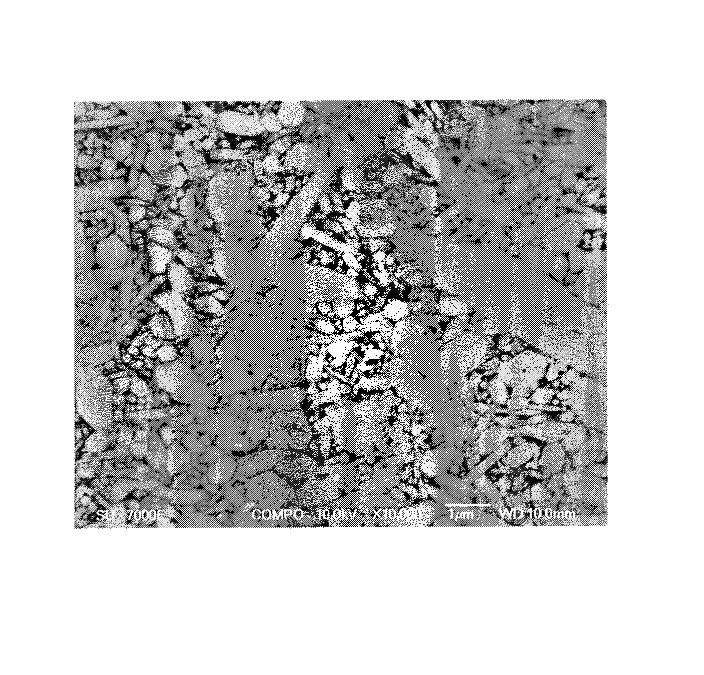
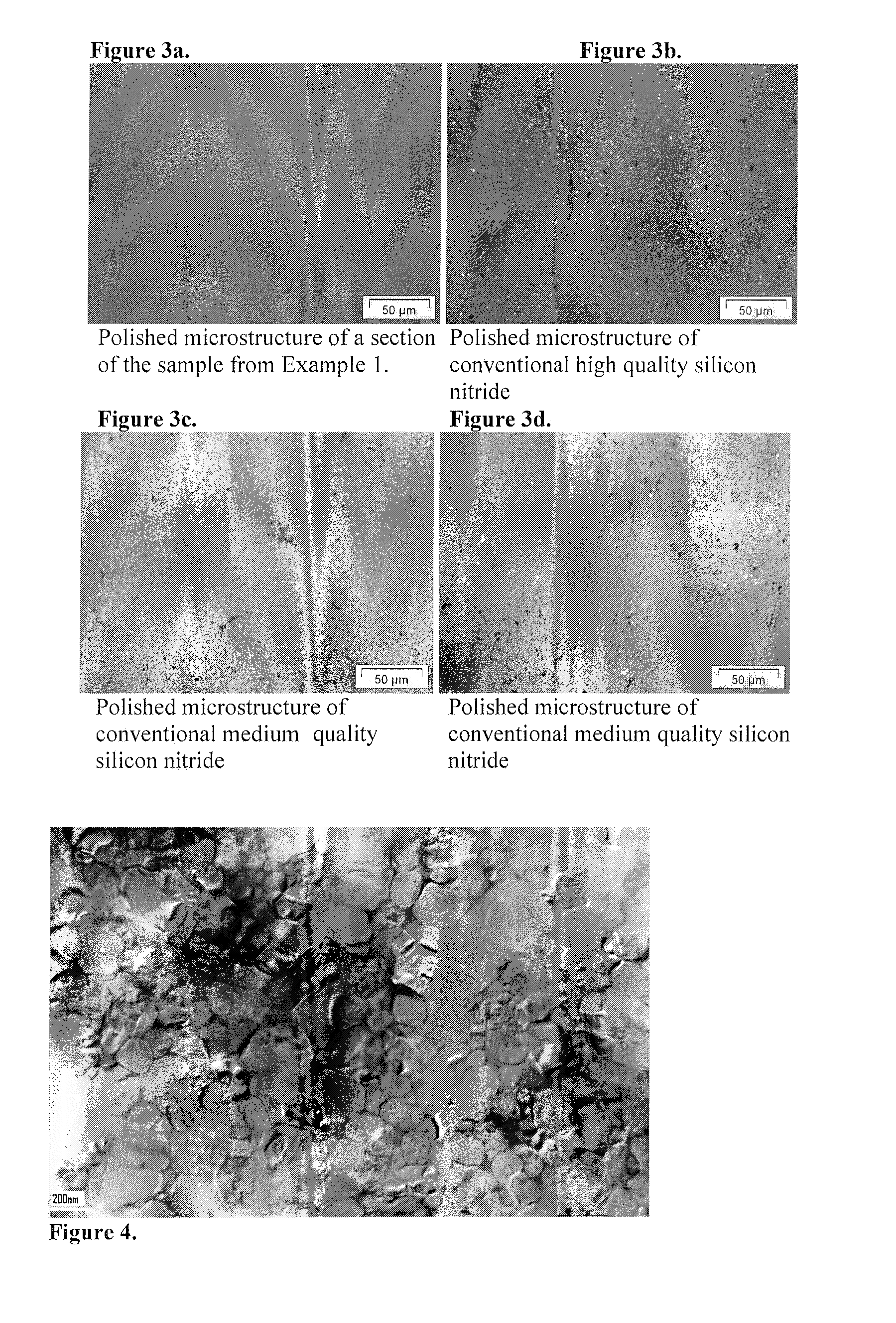
[0048]A powder was produced through mixing of 91 wt % Si3N4 (d502O3 (d506O2N6 (d50−1 was applied. The sample was first densified at 1550° C. for three minutes and thereafter treated at a a second temperature of 1730° C. for five minutes. The temperature was measured with an optical pyrometer focused on the surfaces of the sintering die. The sintering took place under vacuum. The pressure was kept at 50 MPa during the first densification step and was lowered to 5 MPa in the second temperature treatment step.

[0049]A sialon component was formed with a Vicker's hardness, HV10, of about 1800 kg mm−2 and a fracture toughness, K1c, of 6.4-6.8 MPa·m1 / 2. Anisotropy on the fracture indentation toughness was checked and less than 5% between the direction parallel and perpendicular to the pressure direction, the weakest direction still showed minimum fracture indentation toughness above 6 MPa·m1 / 2. 4-point bending strength was estimated, from bi-axial strength tests, to about 810 MPa with a Wei...

example 2

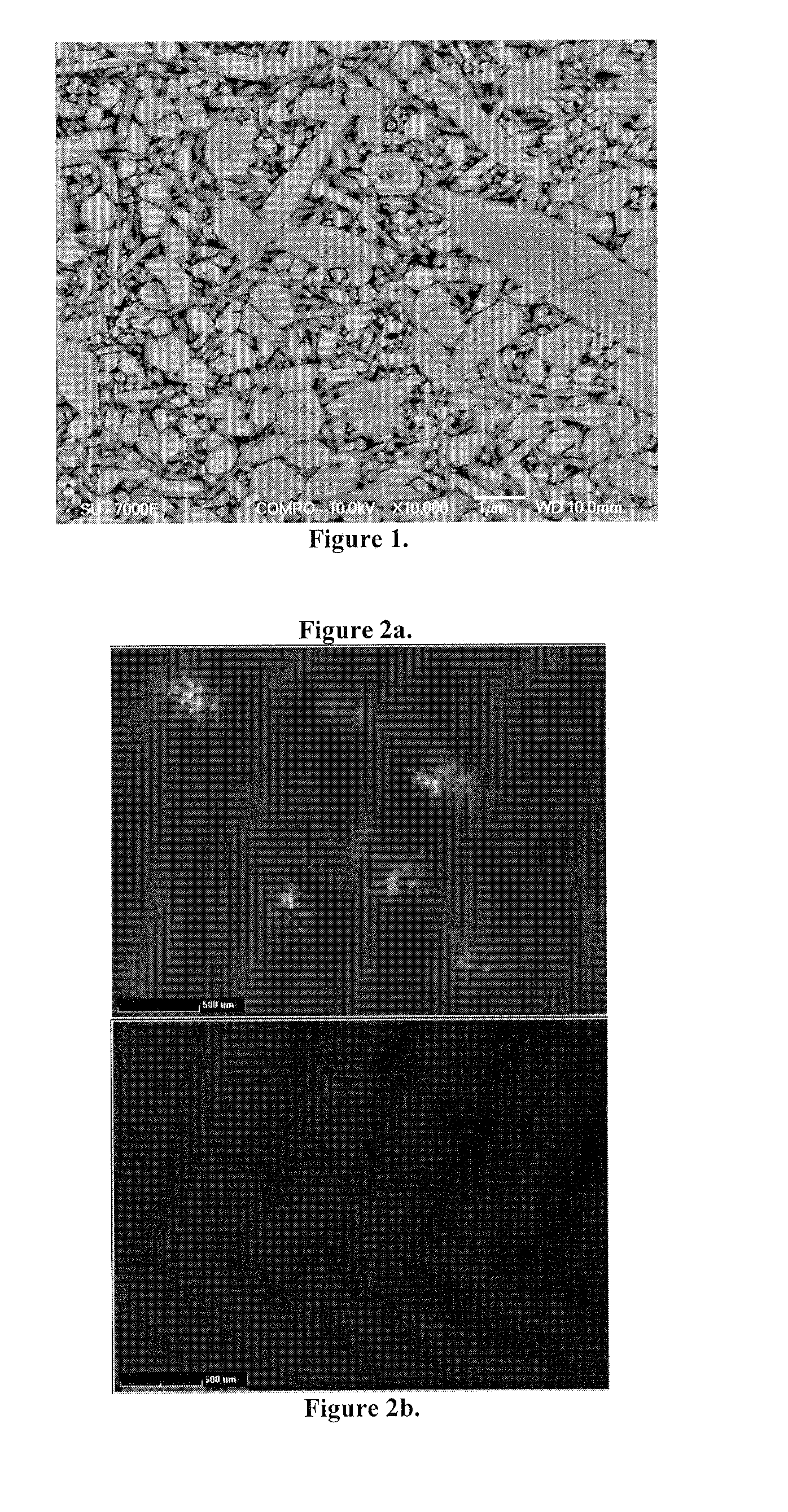
[0051]A powder was produced through mixing of 91 wt % Si3N4 (d502O3 (d50 6O2N6 (d50−1. The sample was densified at 1650° C. for 30 minutes. The temperature was measured with an optical pyrometer focused on the surfaces of the sintering die. The sintering took place under vacuum. The pressure was kept at 40 MPa.

[0052]A sialon component was formed with a Vicker's hardness, HV10, of about 1700 kg mm−2 and a fracture toughness, K1c, of about 6.7 MPa·m1 / 2. Anisotropy on the fracture indentation toughness was checked and less than 11% between the direction parallel and perpendicular to the pressure direction, the weakest direction still showed minimum fracture indentation toughness above 5.7 MPa·m1 / 2. The microstructure showed no visible pores under optical microscopy up to a magnification of 200× on polished samples, limited or no secondary phase and no snowflakes. Only a small 5 mm diameter area in the very core of the component showed few pores with sizes up to 10 μm and a pore fractio...

example 3

[0054]A powder was produced through mixing of 91 wt % Si3N4 (d502O3 (d506O2N6 (d50−1. The sample was densified at 1600° C. for 30 minutes. The temperature was measured with an optical pyrometer focused on the surfaces of the sintering die. The sintering took place under vacuum. The pressure was kept at 40 MPa.

[0055]A sialon component was formed with a Vicker's hardness, HV10, of about 1700 kg mm−2 and a fracture toughness, K1c, of 7 MPa·m1 / 2. Anisotropy on the fracture indentation toughness was checked and less than 11% between the direction parallel and perpendicular to the pressure direction, the weakest direction still showed minimum fracture indentation toughness above 5.7 MPa·m1 / 2. The microstructure showed no visible pores under optical microscopy up to a magnification of 200× on polished samples, limited or no secondary phase and no snowflakes. Only a small 7 mm diameter area in the very core of the component showed few pores with sizes up to 10 μm and a pore fraction volume ...


PUM

PropertyMeasurementUnit
diameteraaaaaaaaaa
timeaaaaaaaaaa
pressureaaaaaaaaaa

Abstract

The invention concerns a sintered ceramic component of silicon nitride or sialon suitable as rolling element in a bearing and a manufacturing method for making such ceramic components. The ceramic component has high density and a homogeneous and fine microstructure, giving the component excellent mechanical properties. Manufacturing of the sintered ceramic component by SPS is cost-effective and rapid.

Description

FIELD OF THE INVENTION[0001]The invention relates to large sintered ceramic components, such as rolling bearing elements, and a method for manufacturing the same.BACKGROUND OF THE INVENTION[0002]Sintered ceramic components are used instead of metallic parts in applications where properties such as high hardness, excellent high temperature behaviour, high thermal shock resistance, low density and high electrical insulating capacity are desired.[0003]Some applications put extreme demands on the components, for example rolling bearings in which contacting parts, between rolling elements and rings, are exposed to high and local stresses. The contacting parts are also exposed to various lubrication, contamination and temperature conditions. Reliable performances and long operating life is critical. So called hybrid bearings consist of ceramic rolling elements and steel based rings with steel, plastic or brass-based cages. Hybrid bearings have shown benefits in certain operation condition...

Claims


Application Information

Patent Timeline
Patent Type & Authority Patents(United States)
IPC IPC(8): C04B35/584C04B35/593C04B35/597C04B35/599C04B35/626C04B35/645F16C33/32
CPCC04B35/593C04B35/597C04B35/62655C04B35/645C04B2235/3217C04B2235/3225C04B2235/3865C04B2235/3869C04B2235/3873C04B2235/5436C04B2235/5445C04B2235/6562C04B2235/6567C04B2235/6581C04B2235/661C04B2235/666C04B2235/767C04B2235/77C04B2235/775C04B2235/78C04B2235/81C04B2235/94C04B2235/95C04B2235/96F16C33/32F16C2206/40F16C2206/60Y10S384/9071
Inventor SHEN, ZHIJIANESMAEILZADEH, SAEIDFLODSTROM, KATARINAVIEILLARD, CHARLOTTE
Owner AB SKF
Why Eureka
Try Eureka