
Isotropic nano crystallites of polytetrafluoroethylene (PTFE) resin and products thereof that are biaxially planar oriented and form stable

a technology of polytetrafluoroethylene and nano crystallites, which is applied in the direction of layered products, electrical generators, transportation and packaging, etc., can solve the problems of poor properties, severe limitation of resin capability, and products produced with pores, and achieves less stringentness, less demanding, and easy manufacturing

Inactive Publication Date: 2014-11-25
ROBERTS FLORENCE
View PDF43 Cites 5 Cited by
  • Summary
  • Abstract
  • Description
  • Claims
  • Application Information

AI Technical Summary

Benefits of technology

The invention provides a way to release nano PTFE crystallites from polymerized dispersion particles and align them in a liquid to form isotropic micro-fibers. These micro-fibers can be deposited on a porous surface to create an interlocking fiber-mat that can be used to fabricate structures. The fiber-mat can be thick and used as a coating without needing a critical cracking thickness. It can also be easily shaped and formed. The invention allows for the continuous processing of PTFE resin into sheet and other products, making it more cost-effective and user-friendly than other resins.

Problems solved by technology

Ever since the discovery of polytetrafluoroethylene (PTFE) polymer researchers have been looking for ways to reduce the particle size of as polymerized PTFE resin, comminuting produced anisotropic particles which required equipment pressures above 2,000 psi that have severely limited the resins capability.
Products produced contained pores and exhibited poor properties that severely restrict PTFE resin utility.
It became evident early that the large polymerized PTFE resin aggregates would require attrition later found to be the root cause for poor moldability and also that water cut coagulated dispersion polymer by Thomas (U.S. Pat. No. 2,936,301) had the same strain instability characteristics; both particle forms were anisotropic with built in memory and a desire to relieve strain when compressed or sintered.
Such pressure is far too high to be economical or practical if used for molding large parts.
), and BHA Group (Atlanta, Ga.) are anisotropic and are an integral part of their product and an irreversible part of the finished sintered product, and all have limited utility in filtering and textiles products.
Anisotropic fibrils are prepared by Friedrich (U.S. Pat. No. 6,352,660), Debe (U.S. Pat. No. 5,910,378), Solomon (U.S. Pat. No. 4,339,325), and Ree (U.S. Pat. No. 4,153,661) but all are highly contaminated with foreign substances mixed or embedded in the product added to induce fibrillation or fiber-like structures that form during long batch processing working the ingredients abrasively in a viscous concentrated mix of hot molten polymer to become embedded into these particulates to contaminate and making it too difficult and costly to extract.
The products have little strength.
The use of a contaminated fluoropolymer in products and / or processes is rare and practically unheard of.
However, the use of contaminated fluoropolymer in chlor-alkali cells is a rare exception as these products have very limited use outside this industry.

Method used


Image

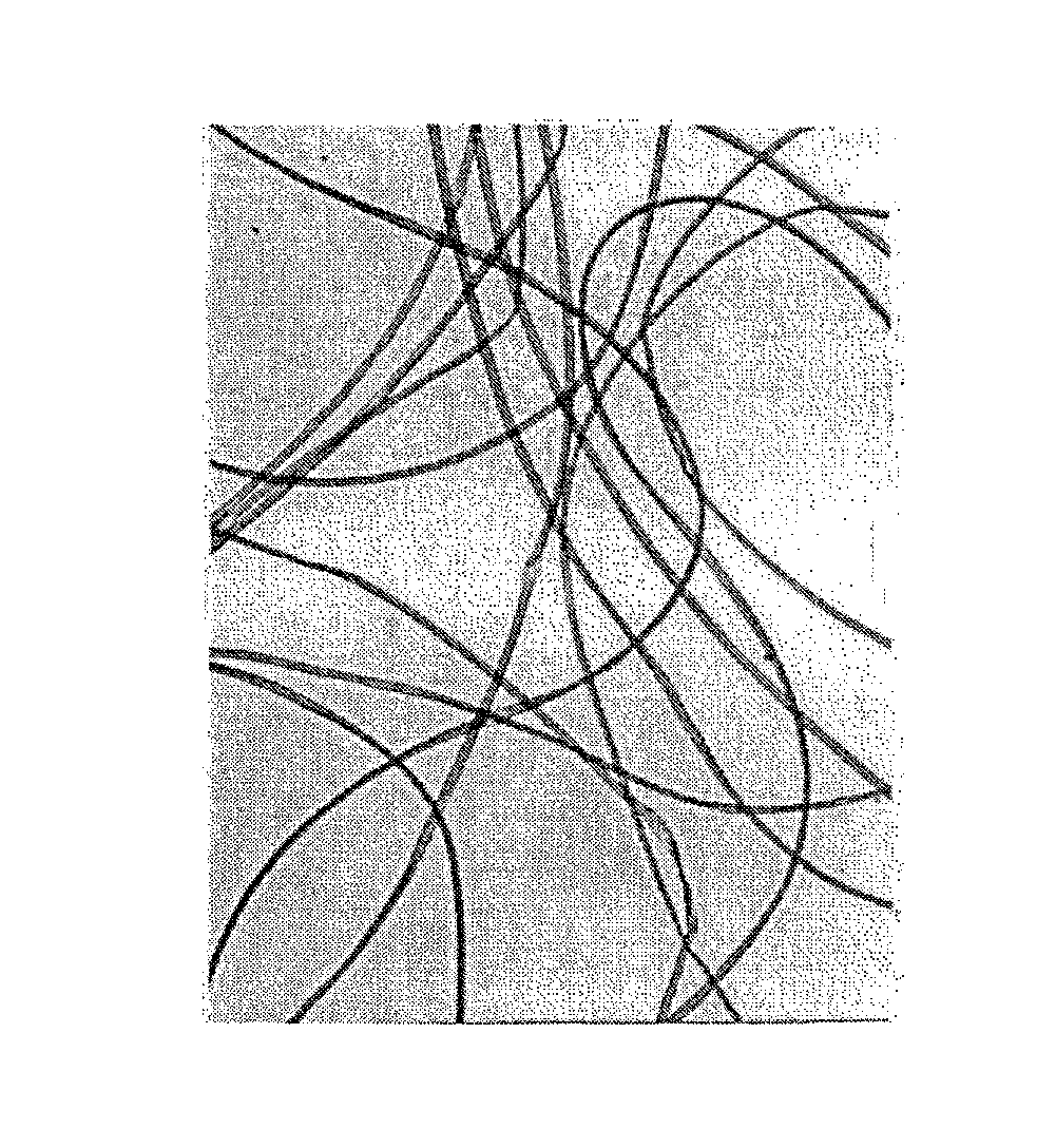
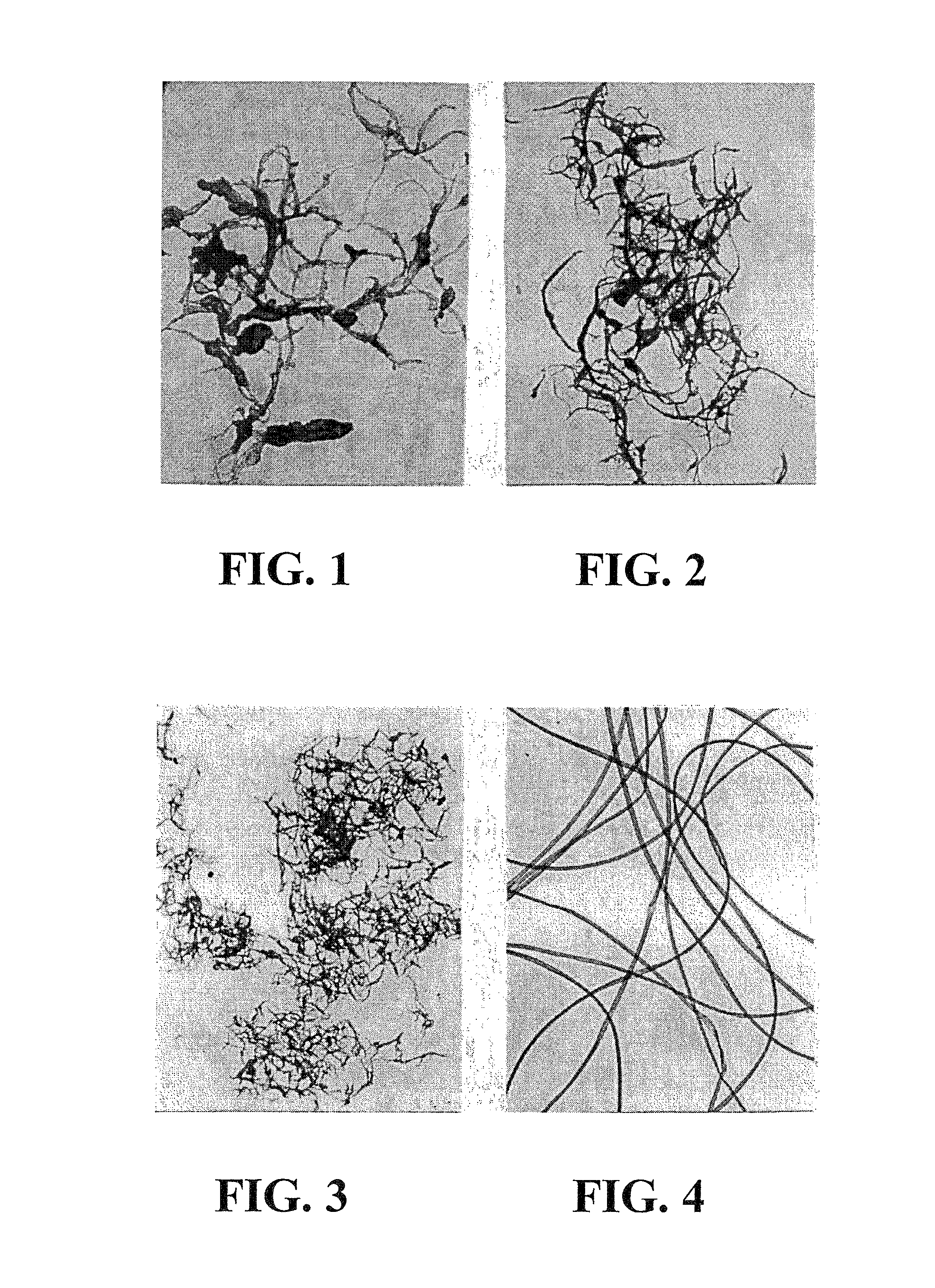
  • Isotropic nano crystallites of polytetrafluoroethylene (PTFE) resin and products thereof that are biaxially planar oriented and form stable
  • Isotropic nano crystallites of polytetrafluoroethylene (PTFE) resin and products thereof that are biaxially planar oriented and form stable
  • Isotropic nano crystallites of polytetrafluoroethylene (PTFE) resin and products thereof that are biaxially planar oriented and form stable

Examples


example 1

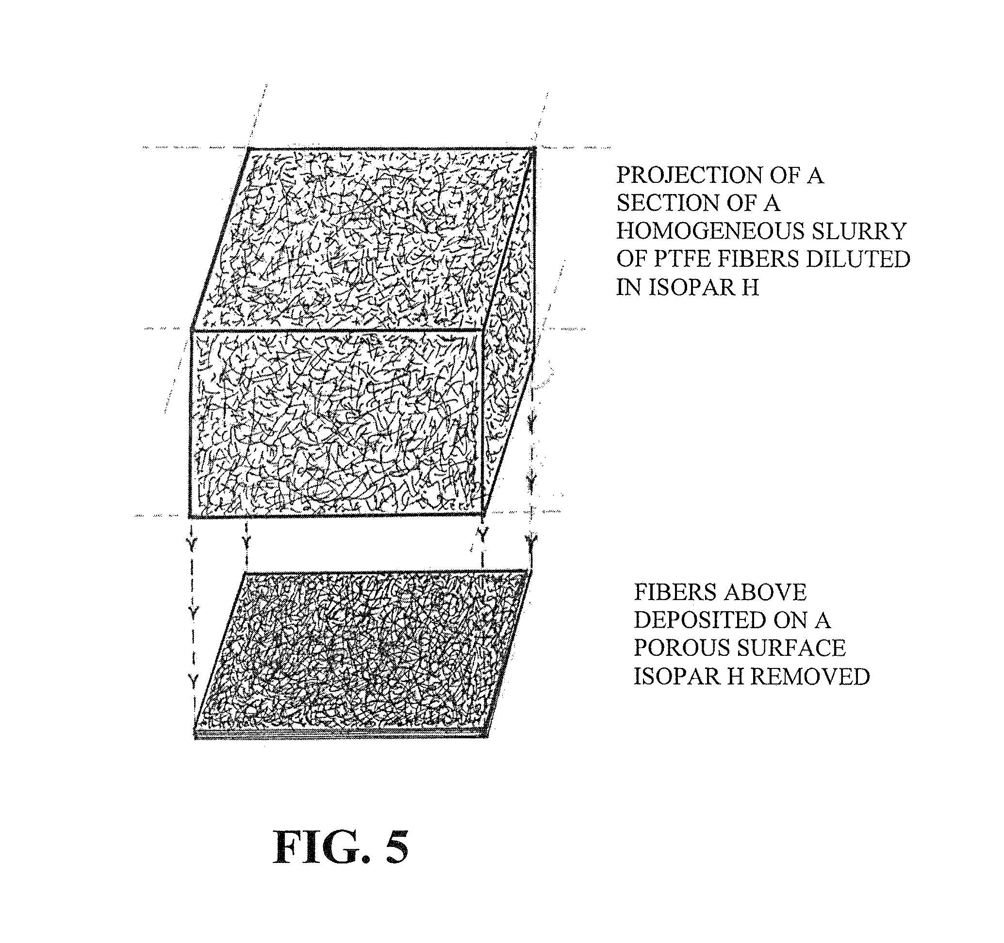
[0054]This example describes changing the structure of isotropic stand-alone colloidal dispersion particles of PTFE resin into isotropic staple length micro-fibers and continuous length fiber product by extracting and rearranging the nano size crystalline content within each dispersion particle; isotropic fiber structures are a new composition of matter for polytetrafluoroethylene (PTFE) resin. Twenty (20) parts of ISOPAR H hydrocarbon oil at 125 degrees centigrade is added to one (1) part of “TEFLON” 6 (DuPont) coagulated dispersion resin (having an average particle size of 500 microns, containing dispersion resin particles 0.05 to 5.0 microns size) said mixture is stirred at a tip rotor speed of 2000 feet / minute, within 3 to 5 minutes a thick slurry of isotropic micro-fibers form that are one quarter inch (¼) to three eights inch (%) long with an average diameter ranging from five (5) to thirty (30) microns long. The thick slurry is diluted further with thirty-five (35) part ambie...

example 2

[0055]This example employs PTFE dispersion particles from an aqueous dispersion rather than coagulated dispersion resin. Slurrying an aqueous dispersion with a water miscible liquid such as an alcohol and removing the water by filtration or by admixing a water-immiscible liquid with aqueous dispersion such as carbon tetrachloride which wets PTFE resin, adding an electrolyte such as hydrochloric acid and stirring until the PTFE resin is transferred into the non-aqueous liquid, decanting the aqueous phase; then filtering the solid PTFE from the carbon tetrachloride to leave PTFE resin.

example 3

[0056]This example describes producing continuous lengths of micro-fiber interlocked sheet product following the method of Example 1 employing coagulated dispersion resin as the PTFE resin feed or alternatively the PTFE dispersion particle feed of Example 2. Once the isotropic micro-fibers are formed according to Example 1 only the slurry is deposited onto a continuous moving porous surface provided with a vacuum similar to those used in papermaking to remove ISOPAR H, then compressed between large diameter (12 to 24 inches in diameter) rolls at low pressure, to consolidate only and not increase “fiber mat” sheet lengths; the consolidated sheet is then dried by infrared heat not to exceed 300 degrees Centigrade followed by sintering by infrared not to exceed 400 degrees Centigrade. The sintered and dried sheet is void free and multi-directional planar oriented isotropic and form stable with a tensile strength of at least four thousand five hundred (4,500) psi and an elongation of at...


PUM

PropertyMeasurementUnit
particle sizeaaaaaaaaaa
pressuresaaaaaaaaaa
pressuresaaaaaaaaaa

Abstract

The subject invention concerns the use of staple length nano polytetrafluoroethylene (PTFE) crystallites obtained by liquid shearing PTFE dispersion particles that are wet by a liquid with a surface tension below 30 dynes / cm this liquid will spread on PTFE resin surfaces and has a contact angle of zero (0) degrees with a PTFE surface. Staple length PTFE resin micro-fibers will form rapidly under high liquid shearing force at 125° C. when diluted 1 part PTFE resin to 20 parts liquid. The subject invention also includes the application of products that are multi-directional planar oriented and isotropic as sheet, membranes and structures useful for high performance filtering, fuel and solar cells and related energy applications. It also concerns products made from formulations as coatings and product for forming, shaping and molding sheet and structures of the subject invention and methods of adhering, bond and laminating components of these structures without adhesives.

Description

CROSS-REFERENCE TO RELATED APPLICATIONS[0001]The present application is a continuation-in-part of application U.S. Ser. No. 11 / 701,901, filed Jan. 31, 2007, now U.S. Pat. No. 7,744,792, which is a continuation-in-part of application U.S. Ser. No. 10 / 401,995, filed Mar. 27, 2003, each of which is hereby incorporated by reference in its entirety including any tables, figures, or drawings.BACKGROUND OF THE INVENTION[0002]Ever since the discovery of polytetrafluoroethylene (PTFE) polymer researchers have been looking for ways to reduce the particle size of as polymerized PTFE resin, comminuting produced anisotropic particles which required equipment pressures above 2,000 psi that have severely limited the resins capability. Products produced contained pores and exhibited poor properties that severely restrict PTFE resin utility. By the time the cause for these limitations was fully recognized the Plunkett patent (U.S. Pat. No. 2,230,654) had expired (1958). No further research dollars w...

Claims


Application Information

Patent Timeline
Patent Type & Authority Patents(United States)
IPC IPC(8): B32B5/16B29K27/18B29C45/00D04H1/00B29C70/04
CPCB29K2027/18B29C45/0005B29C70/04Y10T428/259Y10T428/24628Y10T428/25Y10T428/249924
Inventor ROBERTS, ROBERT
Owner ROBERTS FLORENCE
Learn More