PLGA/HA hydroxyapatite composite bone grafts and method of making

a technology of hydroxyapatite and composite bone grafts, which is applied in the field of hydroxyapatite/ha composite bone grafts and the making field, can solve the problems of rapid degradation and leave voids formerly occupied by sodium chloride particles, and achieve the effects of fast, high-quality, uniform coating, and improved bone cell propagation and ingrowth

Inactive Publication Date: 2015-04-14
THIERRY GIORNO
View PDF8 Cites 7 Cited by
  • Summary
  • Abstract
  • Description
  • Claims
  • Application Information

AI Technical Summary

Benefits of technology

[0002]This invention is a novel biomaterial including formed shapes that are especially useful in tissue engineering applications involving bone. The composite comprises a polymeric scaffold, most preferably poly(D,L-lactic-co-glycolic acid) (PLGA) and particles of a bioactive bioceramic such as hydroxyapatite (HA), triCalcium phosphate (TCP), calcium sulfate or bioglass or a combination thereof, wherein the ceramic is highly exposed on the biomaterial surface. In one embodiment, a collagen solution is forced or infused through the biomaterial using pressure, centrigution or a vacuum. A further embodiment of this invention involves a ceramic, such as apatite, that is fastly, highly, and uniformly coated on the biomaterial surface. This new biomaterial is advantageous because it promotes bone cell propagation and ingrowth better than current materials. The biomechanical properties of this biocomposite in block form are far superior to hydroxyapatite blocks, or even to the natural bone. The material when milled is also suitable for use as a powder or granular material as a bone filler or cement, for filling spaces from a few mm3 in volume to larger cm3. Volumes of bone needing replacement can be measured using imaging technology and exact replacements produced through computer-aided design (CAD) in conjunction with computer aided manufacturing (CAM).

Problems solved by technology

Optionally, an additional porogen can be used to form pores, but such additional porogens have been found to created too much surface area in the PLGA leading to rapid degradation.
If present, the optional sodium chloride particles are subsequently leached out of the material by immersing the scaffold in distilled water for a sufficient amount of time to dissolve the salt, thus leaving voids formerly occupied by the sodium chloride particles.

Method used


Image

  • PLGA/HA hydroxyapatite composite bone grafts and method of making
  • PLGA/HA hydroxyapatite composite bone grafts and method of making
  • PLGA/HA hydroxyapatite composite bone grafts and method of making

Examples


example 1

Process

[0064]L-Lactide / caprolactone copolymer / HA TCP composites were prepared with 75:25 Lactide / caprolactone copolymer particles (diameter=100-200 μm μm, molecular weight=100,000 Da, Purac Biomataerials), HA TCP particles (diameter=approximately 100-1000 nm, 40% HA to 60% TCP). The polymer particles were mixed with the HA TCP particles. The polymer / HA TCP mass ratio ranged from 80:20 to 50:50 polymer to HA TCP by weight. The mixture was loaded into a mold and exposed to high pressure CO2 gas (2000 psi) for 3-4 hours to saturate the polymer with the gas. Temperature in the reaction vessel is maintained at around 200 degrees F. to maintain CO2 in the supercritical range. Then, decreasing the gas pressure to ambient pressure created a thermodynamic instability which led to the nucleation and growth of CO2 pores within the polymer scaffolds.

[0065]The specific ratios of polymers is not critical, but plays a role in absorption. 50:50 ratios of co polymers tend to absorb faster. Changing ...

example 2

Powder

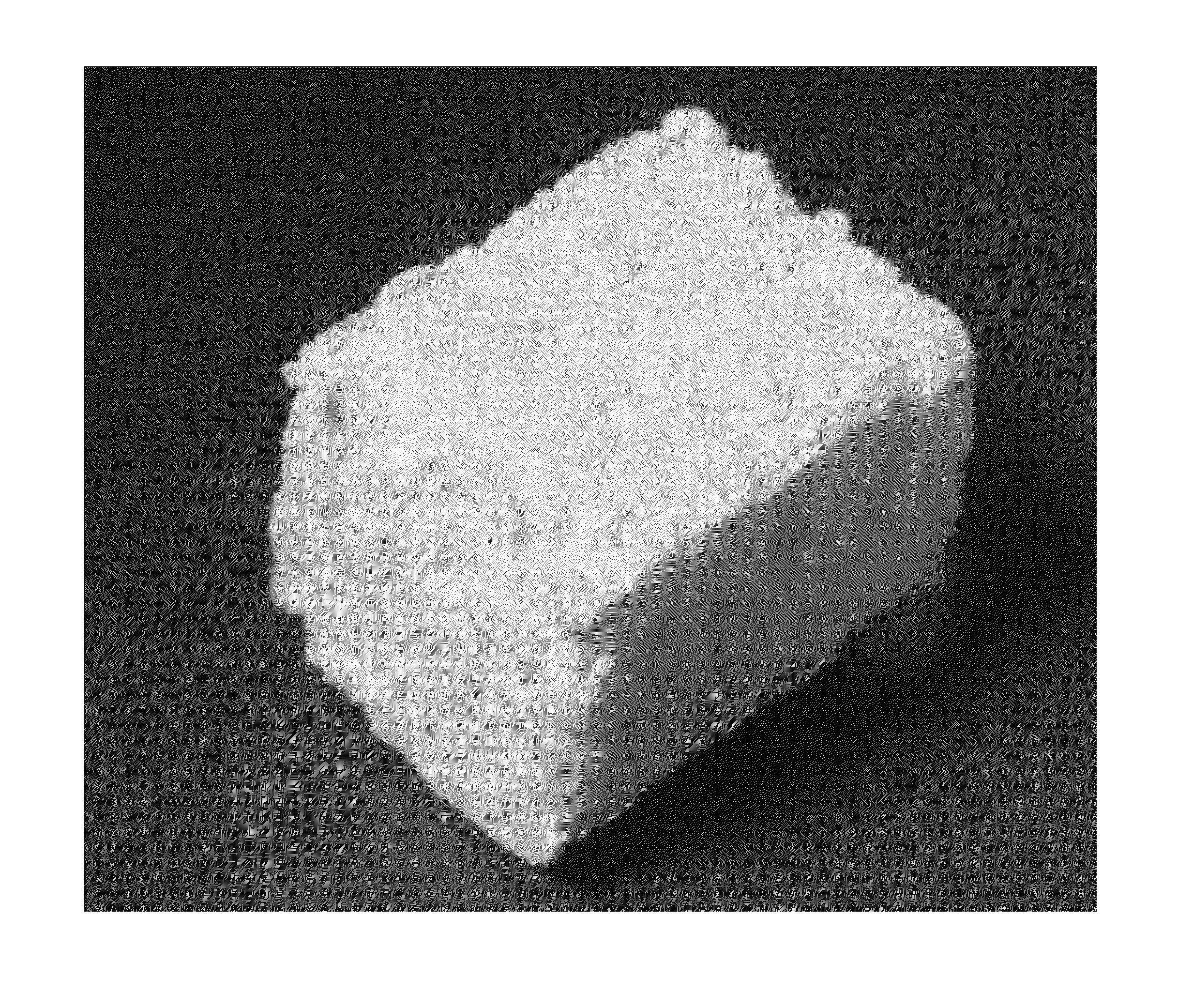
[0097]PLGA / HA scaffolds were created using the process of Example 1 and were ground to a powder sized between about 250 nm and about 2 mm. Most preferable the powder is graded into two different sizes of particles, the smaller consisting particles between about 250 nm and about 750 nm and the larger being between about 750 nm and about 2 mm. The resultant material can be used to pack surfaces around devices implanted in bone and packed in voids in bone to induce new bone growth. FIG. 14 is a photograph of the bone graft in powder form.

[0098]Those of skill in the art are familiar with the use of bone graft materials. The present invention can be used in the same manner as any other bone graft material. In a preferred delivery system, the bone graft material is mixed with polyethylene glycol or another hydrogel to form a paste. The material can be premixed and sold in a syringe for easy application or can be mixed at the point of use and delivered via any convenient means. When ...

example 3

Molded Bone Grafts

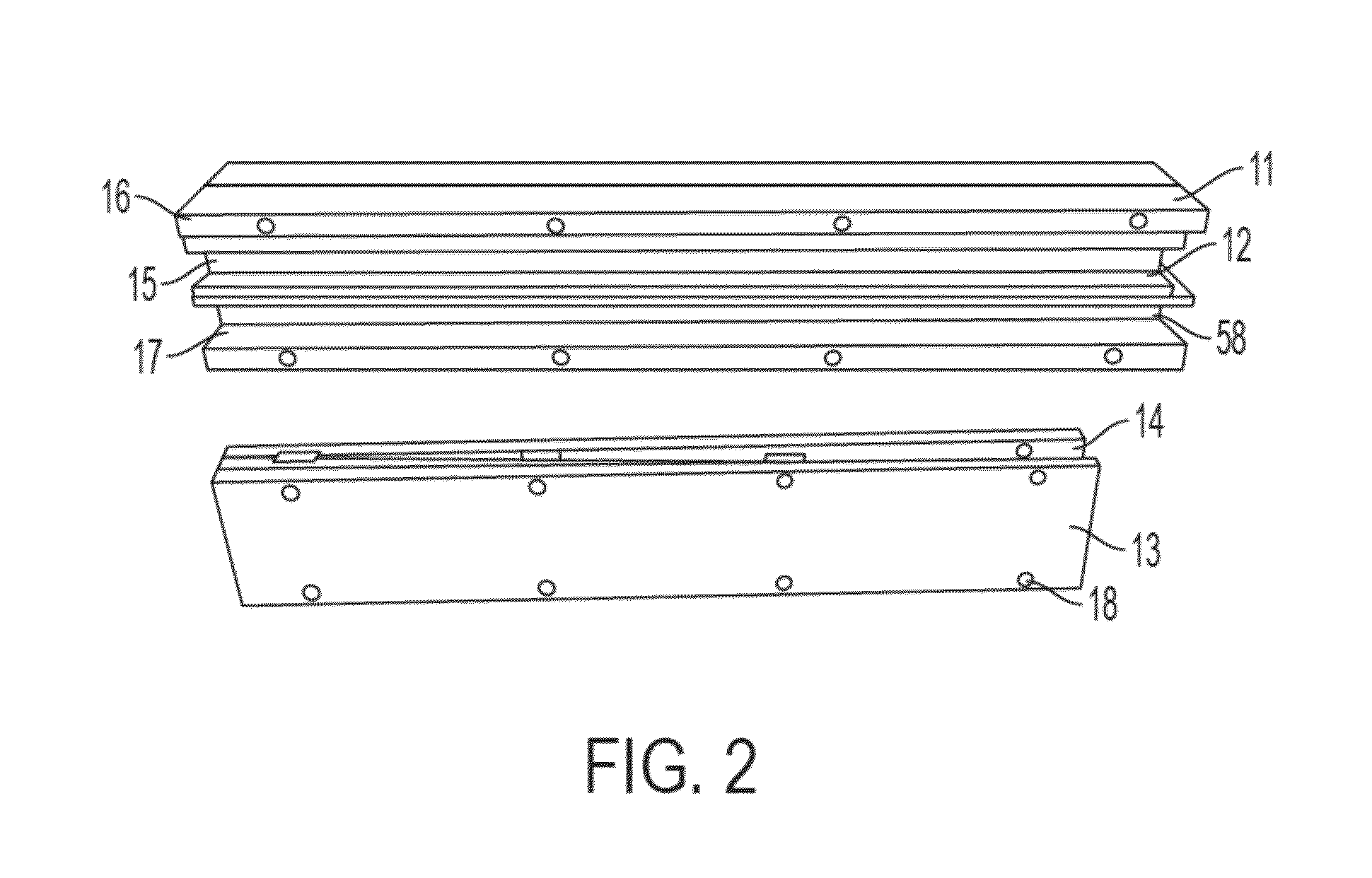
[0100]The scaffold of Example 1 can be molded into a rigid implantable bone graft material of desired shapes by creating an appropriate mold for use in the reaction vessel. Referring to FIG. 2-7, the mold 11 consists of a bottom 40 and a right side 16 and a left side 17 which define a void 23. End caps 24 are placed at each end and a top cap 14 closes the mold. The shape of the void 23 determines the final shape of the bone graft 10. The mold can be designed to produce a single implant or can be designed to produce multiple implants. In the figures the mold contains a divider for producing two implants. One of skill in the art will appreciate that the mold can be designed to create bone grafts having complex shapes as well as simple geometric shapes. In the Figures, the molds are assembled using screws 22 although clamps or shaping the mold so it is evenly supported in the pressure vessel can also be used. When screws 22 are used, the top cap 14 and end caps 24 wil...


PUM

PropertyMeasurementUnit
diameteraaaaaaaaaa
diameteraaaaaaaaaa
diameteraaaaaaaaaa

Abstract

The present invention involves tissue engineering constructs made from a new composite bone graft material made from biocompatible poly(D,L-lactic-co-glycolic acid) (PLGA) and bioceramic particles exposed on its surface using a gas foaming particle leaching (GF / PL) method and infused with collagen. Methods and apparatus for of forming scaffolds are also disclosed.

Description

[0001]This application claims priority to U.S. provisional patent application No. 61 / 601,128 filed on Feb. 21, 2012 and cross references and incorporates by reference patent application Ser. No. 12 / 279,172, PCT / US2007 / 05693, Ser. No. 12 / 279,172 and 60 / 767,137. The contents of all references, patents and patent applications are expressly incorporated by reference.SUMMARY OF THE INVENTION[0002]This invention is a novel biomaterial including formed shapes that are especially useful in tissue engineering applications involving bone. The composite comprises a polymeric scaffold, most preferably poly(D,L-lactic-co-glycolic acid) (PLGA) and particles of a bioactive bioceramic such as hydroxyapatite (HA), triCalcium phosphate (TCP), calcium sulfate or bioglass or a combination thereof, wherein the ceramic is highly exposed on the biomaterial surface. In one embodiment, a collagen solution is forced or infused through the biomaterial using pressure, centrigution or a vacuum. A further embodi...

Claims


Application Information

Patent Timeline
Patent Type & Authority Patents(United States)
IPC IPC(8): A61F2/28A61L27/40A61L27/46A61L27/56
CPCA61L27/40A61F2/28A61L27/46A61L27/56C08L67/04A61L2400/12A61L2430/02A61L27/26A61L27/365A61L27/3691A61L27/54A61L2400/18B29C33/3835B29C33/62B29C43/14B29K2027/18B29K2067/043B29K2067/046B29K2089/00B29K2105/0088B29K2509/02B29L2031/7532
Inventor GIORNO, THIERRY
Owner THIERRY GIORNO
Why Eureka
Try Eureka