Method for quantifying local bone changes

a local bone and change technology, applied in the field of local bone change quantification, can solve the problems of periapical bone loss inflammation, tooth loss, tooth loss, etc., and achieve the effect of avoiding the formation of buccal and oral bone, and avoiding the formation of periapical bon

Active Publication Date: 2015-05-19
NOBEL BIOCARE SERVICES AG
View PDF13 Cites 7 Cited by
  • Summary
  • Abstract
  • Description
  • Claims
  • Application Information

AI Technical Summary

Benefits of technology

[0018]It is an object of the present invention to provide a method for volumetric quantification of local bone or soft tissue loss which makes it possible to solve one or more of the problems of the state of the art. It is an advantage of embodiments according to the present invention that efficient methods using semi-automatic segmentation and / or image registration are provided. The image registration may comprise transforming datasets, for instance a bone graft site scan just after surgery and after 6 months, to 1 coordinate system.
[0019]It is an advantage of at least some embodiments that algorithms can be applied for determining and comparing precisely the region of interest where the bone loss may be present. It is an advantage of at least some embodiments of the present invention that accurate and fast methods and systems for selecting and comparing bone volume regions of interest are provided.
[0020]It is an advantage of at least some embodiments of the present invention that a small or minimized region of interest can be selected because of the number of artifacts that typically is present in e.g. (CB)CT and because of intensity deviations in pre and post scans. It is an advantage that for example not the whole jaw or no large part of the jaw is to be taken into account as this could contain too many errors for accurate segmentation.
[0021]It is an advantage of at least some embodiments of the present invention that a universal method for selecting region of interest is provided thus bringing a standardized method for accurate follow-up of bone change and for validating the outcome of several clinical therapies in Periodontology. The latter may be especially advantageous for local bone change around a tooth or implant or for bone augmentation techniques in a small region.
[0048]It is a further object of the present invention to provide a method for selecting a region of interest in a (cone beam) CT scan or 3D image which makes it possible to solve one or more of the problems of the state of the art. The method of the present invention for selecting a region of interest in a (cone beam) CT scan or 3D image comprising the following steps selecting a set of anatomical landmarks in said 3D image, on the basis of said anatomical landmarks constructing 6 clipping planes (clipping box) which construct a volume in said 3D image, said volume being the region of interest and removing all data from the 3D image outside the region of interest (cropping)

Problems solved by technology

This bone loss (resulting in pocket formation between the teeth and the remaining soft tissues or bone) may affect one to all teeth and eventually, when left untreated, lead to tooth loss.
Furthermore, bacteria in the plaque may cause caries reaching the pulpal tissues of the teeth and cause periapical (around the apex or root point of the tooth) inflammation with periapical bone loss.
However, these radiographs project all periodontal structures on top of each other, which make differentiation of buccal and oral bone hardly impossible.
In addition, if the x-ray's are not pointed perpendicular to the receptor, bone levels can be misinterpreted because of projection errors.
Thus, one of the main drawbacks of intra-oral radiography is overlap of anatomical structures and lack of three-dimensional (3D) information.
This often hinders a true distinction between the buccal and lingual cortical plate and complicates the evaluation of periodontal bone defects, especially the infrabony lesions, also denoted as craters, and furcation involvements (bone loss at the furcation).
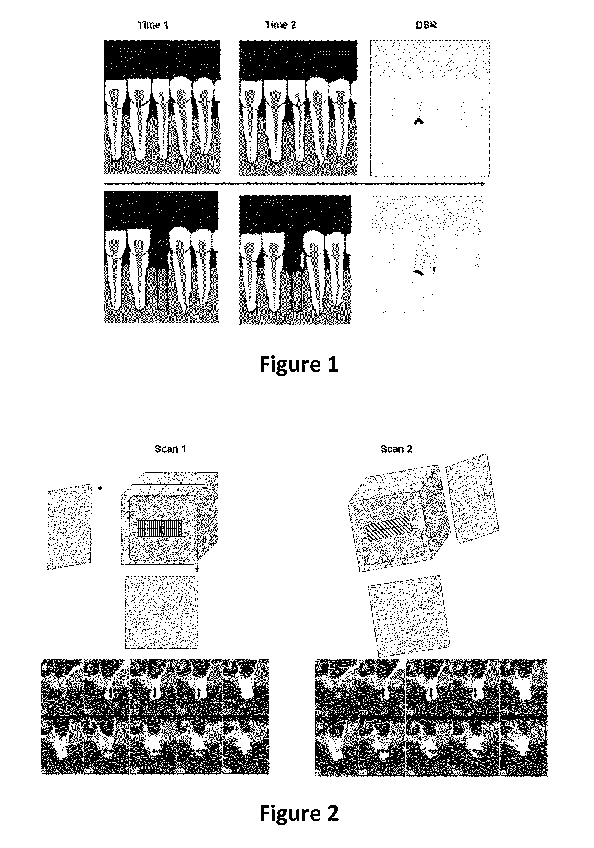
To determine the result of these therapies, the current 2D projection radiographs form an additional problem.
Unfortunately, it is critical to use the same projection angle at both moments, so individualized bite blocks need to be fabricated per patient to follow up the bone.
Also, this digital subtraction radiography (DSR) does not provide any 3D information.
The same principle applies when investigating bone lesions around the root end (apex) of a tooth, where 2D projection radiographs often causes misdiagnosis since the buccal and oral bony plates may project onto these local lesions inside the bone.
When periodontal disease progresses, severe bone loss can lead to tooth loss.
Although the critical importance of reducing projection errors with two-dimensional radiographs and using an optimal radiographic protocol, the current literature describing radiographic follow-up in details is sparse.
Inter- and intra-observer variability is seldom explored and new three-dimensional techniques are still not commonly used.
The same problem is seen when using bone augmentation techniques (bone grafting and ridge preservation).
Implant-therapy has several obstacles that can influence its use or success-rate.
. . but contradictory results are often demonstrated.
This indicates that the choice of augmentation and implant therapy is very complex, and that in addition it is complicated by the continuous technological innovation—on implant as well as bone augmentation level.
Unfortunately, volumetric quantification of bone still has only been employed a few times and rarely for volumetric follow-up of bone loss.
Often widths and heights are measured on 2D slices, as e.g. discussed in Chen et al. J. Periodontal 2008 (79) 401, which is better than on projection radiographs, but still this shows a severe limitation since all the above bone remodelling processes are in three dimensions.
This is very cumbersome.
For instance, manual slice by slice segmentation of structures can be very user dependent and time consuming, especially when two volumes in time need to be processed.
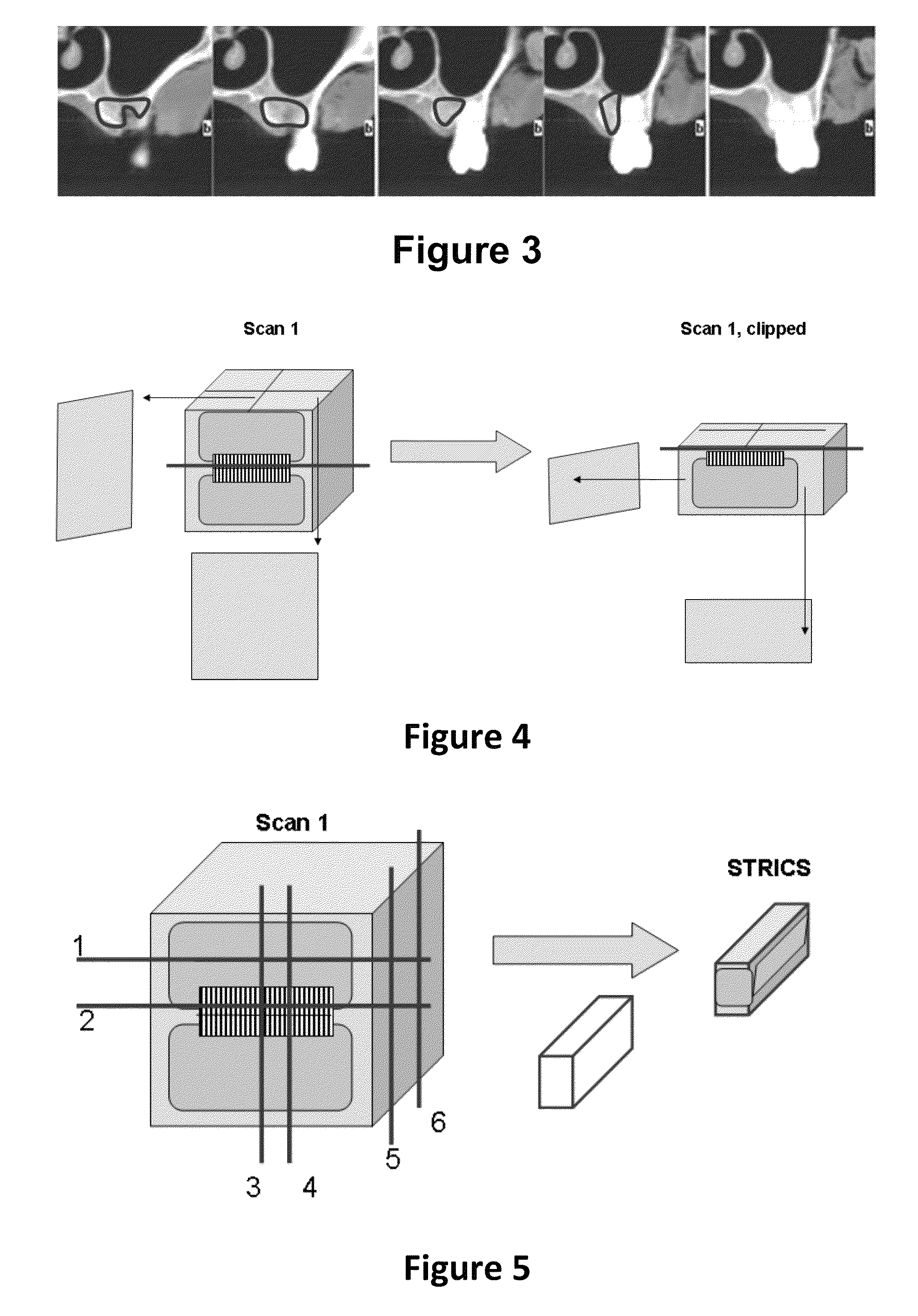
Especially the segmentation of bone grafts can be quite difficult because of limited visibility on (CB)CT volumes, as indicated for example in Beaman et al.
Without an accurate, efficient and universal volume determination method, the optimal bone grafting technique for implant therapy can not be investigated.
It thus becomes difficult using the existing methods for answering for example the question which bone graft method of a given selection results in less bone loss.
However, this bone remodelling is a dynamics process over time, which needs an accurate follow-up.
In addition to the fact that this is only a part of the bone loss that can be assessed (height loss at 1 point while the volume should be assessed), projection errors may project the bone at differently than the actual situation.
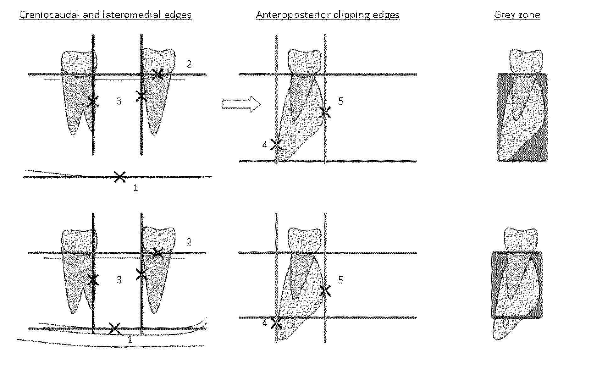
In addition, horizontal measurements can now also be made, where the width (arrows in FIG. 2) of the alveolar ridge can be measured, which is not possible on a 2D projection.
The major problem here is that a lot of measurements per tooth need to happen, with again the precise standardization required.
This makes assessment of the whole volume almost impossible.
Again, this results in insufficient volume information for follow-up and it is rather time consuming.
Because of all these limitations it is also very difficult to validate periodontal therapies—from rootplaning to bone augmentation and implant therapy.
This makes it of course also very difficult to precisely follow-up periodontal patients.
Drawbacks are of course the intensive labour required, operator bias and difficulty in obtaining reproducible results.
In this way, volume 1 and 2 will both be influenced by these limitations, resulting in inadequate follow-up of bone volumes.

Method used


Image

  • Method for quantifying local bone changes
  • Method for quantifying local bone changes
  • Method for quantifying local bone changes

Examples


example 1

[0133]By way of illustration, embodiments of the present invention not being limited thereby, an experimental example is discussed below, illustrating features and advantages of embodiments of the present invention. The example illustrates, for the determination of the bone volume follow-up method, an in-vitro pre-test whereby accuracy is evaluated (see FIG. 16). A dry skull with soft tissue simulation modelled over the jaws served as subject. A defect was created with a round steal bur at the maxillary left central incisor level to simulate bone loss. A pre-scan was first taken before defect creation. After defect creation (with buccal occlusal keys to preserve the buccal contour), heated wax modelled into the defect and covered with the buccal key. In this wax, a negative of the defect could be created. Then, the obtained defect key was optically scanned with a laser scanner at a resolution of approximately 40 micron. Now the volume of the defect could be calculated in mm3 and a p...


PUM


Abstract

A method and system for volumetric quantification of local bone changes includes the steps of loading at least a first and second (cone-beam) computed tomography three dimensional image, registering the first three dimensional image and second three dimensional image to one coordinate system, selecting a region of interest in one of the first three dimensional image or the second three dimensional image. For the first three dimensional image and the second three dimensional image, segmenting the local bone within the region of interest by segmenting voxels related to air and / or soft tissues within the region of interest and attributing these voxels to an outside region, while the volume formed by the remaining volume represent the local bone or the local bone with soft tissue, and calculating of the volume of local bone in the first three dimensional image and the volume of local bone in the second three dimensional image and subtracting the first volume from the second volume and defining the difference as the local bone change or the change in local bone with soft tissue.

Description

FIELD OF THE INVENTION[0001]The present invention relates to methods and systems for volumetric quantification of local bone or soft tissue loss or gain and methods for determining a region of interest in 3D image data. Bone / soft tissue loss is an important clinical criterion for determination of the success-rate of the following dental therapies: periodontal therapy, bone augmentation or grafting techniques, implant therapy, endodontic therapy or orthodontic therapy.BACKGROUND OF THE INVENTION[0002]Periodontal disease is the most common oral disorder in the elderly population and showing an increasing incidence with age. It consists of several disorders of the periodontium (tissues surrounding the teeth), including gingivitis and periodontitis, which are chronic infectious diseases. The presence of certain bacteria initiate plaque and calculus formation supra- and subgingival (above and under the gums), which affects the soft tissues (gums) surrounding the teeth and causes inflamma...

Claims


Application Information

Patent Timeline
Patent Type & Authority Patents(United States)
IPC IPC(8): G06K9/00A61B5/055A61B6/00A61B6/14G06T7/00G06T11/00
CPCG06T11/003A61B6/14A61B6/4085A61B6/466A61B6/469A61B6/486A61B6/5217A61B6/5235G06T7/0016A61B5/055G06T2207/10081G06T2207/20101G06T2207/20141G06T2207/30036G06T7/187G16H50/30
Inventor VANDENBERGHE, BART
Owner NOBEL BIOCARE SERVICES AG
Why Eureka
Try Eureka