

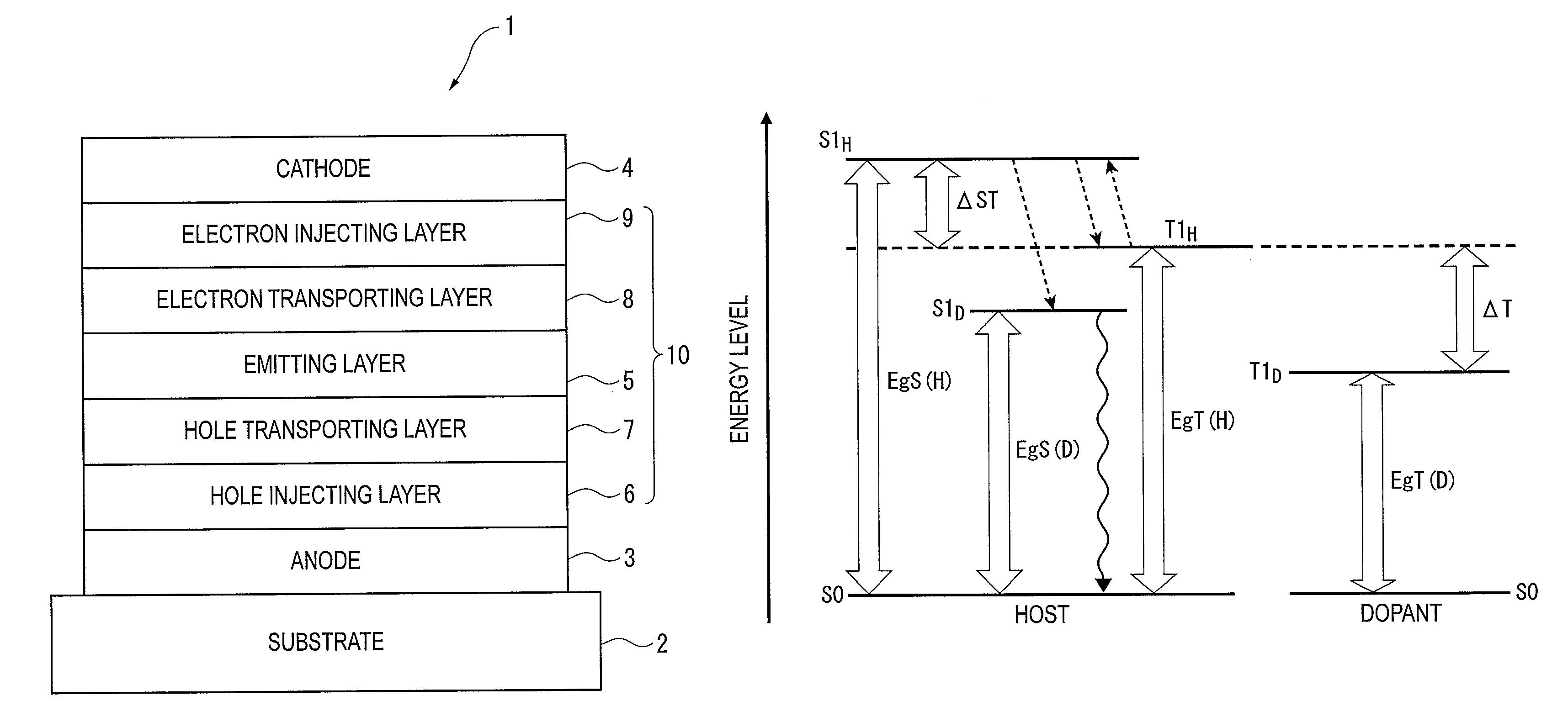
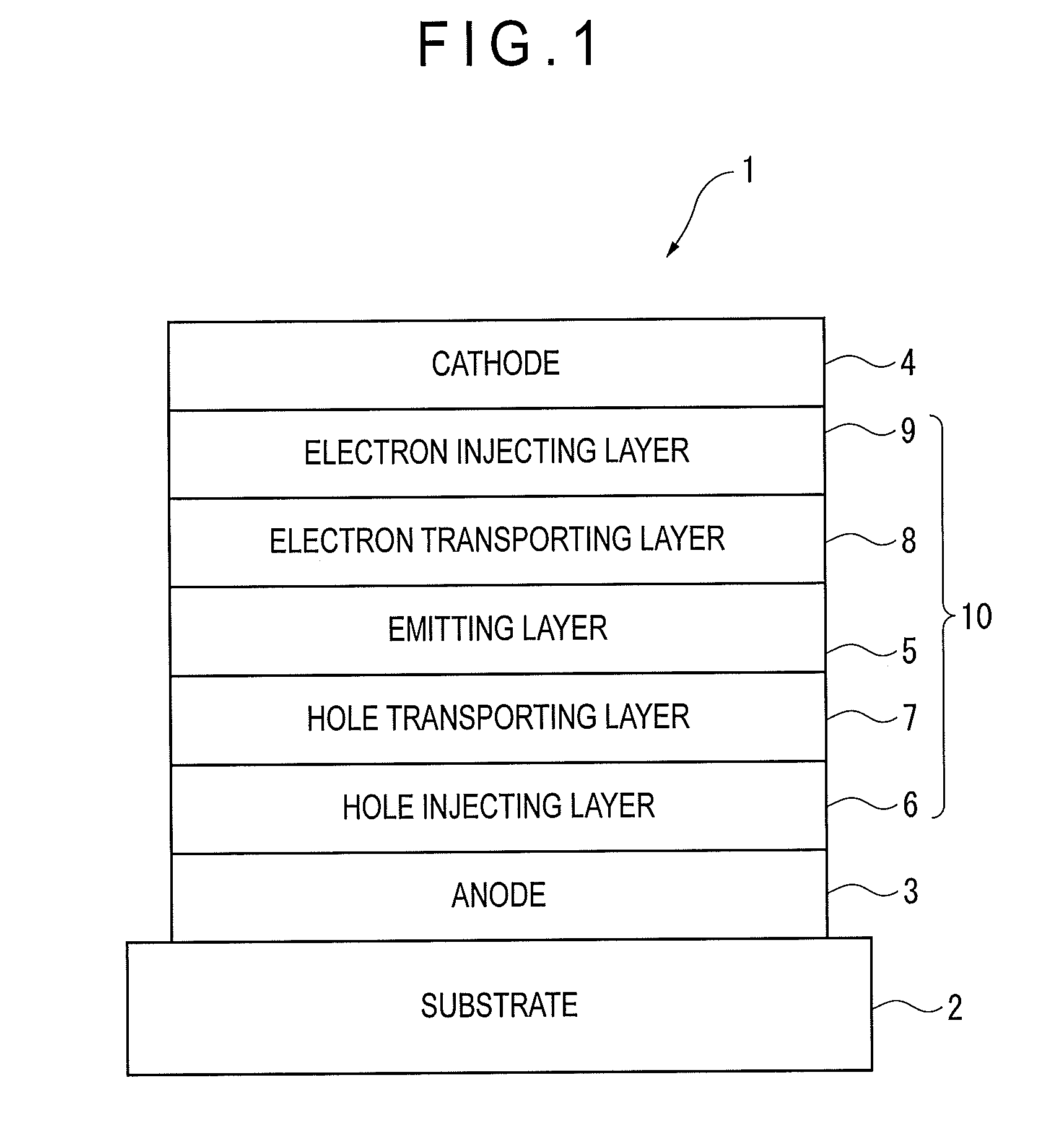
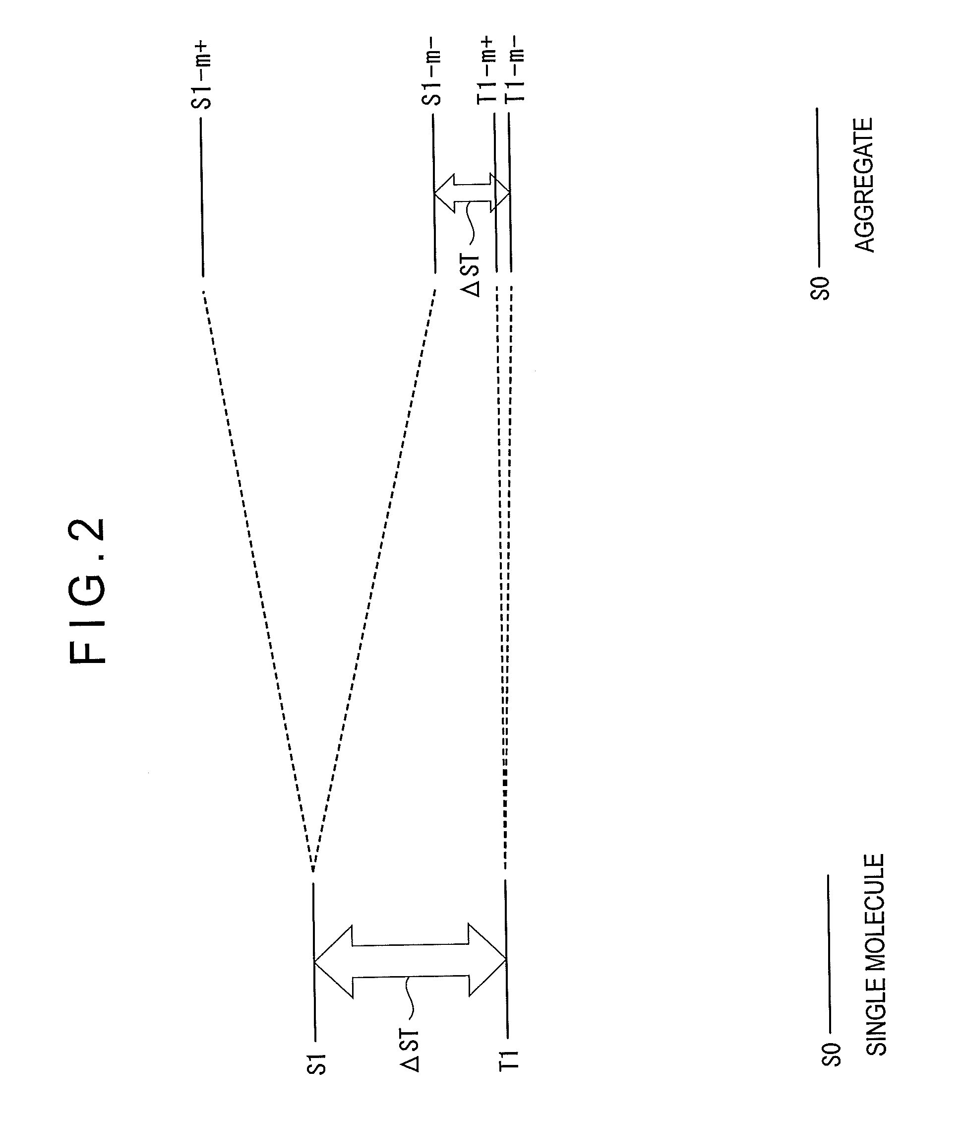
Organic electroluminescence device
a technology of electroluminescence and electroluminescence, which is applied in the direction of luminescent compositions, organic chemistry, chemistry apparatus and processes, etc., can solve the problems of many practical problems in using delayed fluorescence by the tadf mechanism, and the problem of improving efficiency of fluorescence emission is still problemati
- Summary
- Abstract
- Description
- Claims
- Application Information
AI Technical Summary
Benefits of technology
Problems solved by technology
Method used
Image

Examples
synthesis example 1
Synthesis of H-1
(1-1) Synthesis of Intermediate Body 1
[0371]Under an argon gas flow, 2-nitro-1,4-dibromobenzene (11.2 g, 40 mmol), phenylboronic acid (4.9 g, 40 mmol), tetrakis(triphenylphosphine)palladium (1.39 g, 1.2 mmol), toluene (120 mL) and an aqueous solution of 2M sodium carbonate (60 mL) were added together in sequential order, and heated to reflux for 8 hours.
[0372]After the reaction solution was cooled down to the room temperature, an organic layer was separated and an organic solvent was distilled away under reduced pressure. The obtained residue was refined by silica-gel column chromatography, so that the intermediate body 1 (6.6 g, a yield of 59%) was obtained. As a result of FD-MS (Field Desorption Mass Spectrometry) analysis, the reactant was identified as the intermediate body 1.
[0373]
(1-2) Synthesis of Intermediate Body 2
[0374]Under an argon gas flow, the intermediate body 1 (6.6 g, 23.7 mmol), triphenylphosphine (15.6 g, 59.3 mmol), and o-dichlorobenzene (24 mL) w...
synthesis example 2
Synthesis of H-2
(2-1) Synthesis of Intermediate Body 4
[0385]An intermediate body 4 was synthesized according to the same method as that for the synthesis of the intermediate body 1, except for using 1-bromo-4-iodebenzene in place of 2-nitro-1,4-dibromo-1-benzene and 9-phenyl-9H-carbazole-3-ylboronic acid in place of phenylboronic acid. As a result of FD-MS (Field Desorption Mass Spectrometry) analysis, the reactant was identified as the intermediate body 4.
(2-2) Synthesis of Intermediate Body 5
[0386]
[0387]Under argon gas flow, the intermediate body 4 (10 g, 25 mmol), bis(pinacolato)diboron (8.3 g, 33 mmol), [1,1′-bis(diphenylphosphino)ferrocene]palladium (II) dichloride dichloromethane adduct (0.62 g, 0.75 mmol), potassium acetate (7.4 g, 75 mmol) and N,N-dimethylformamide (170 mL) were sequentially mixed, and heated to reflux for eight hours.
[0388]After the reaction solution was cooled down to the room temperature, an organic layer was separated and an organic solvent was distilled...
synthesis example 3
Synthesis of H-3
[0397]H-3 was synthesized in the same manner as H-1, except that 4′-bromobiphenyl-3-carbonitrile was used in place of 4-bromo-4′-cyanobiphenyl.
[0398]FD-MS (Field Desorption Mass Spectrometry), maximum ultraviolet absorption wavelength λmax and maximum fluorescence emission wavelength in a toluene solution of the obtained compound are as follows.
[0399]FDMS, calcd for C43H27N3=585. found m / z=585 (M+)
[0400]UV(PhMe); λmax, 322 nm, FL(PhMe, λex=300 nm); λmax, 376 nm
[0401]
PUM
| Property | Measurement | Unit |
|---|---|---|
| internal quantum efficiency | aaaaa | aaaaa |
| internal quantum efficiency | aaaaa | aaaaa |
| internal quantum efficiency | aaaaa | aaaaa |
Abstract
Description
Claims
Application Information