Formed electrical contact pad for use in a dual stage actuated suspension

Active Publication Date: 2015-08-11
MAGNECOMP
View PDF29 Cites 11 Cited by
  • Summary
  • Abstract
  • Description
  • Claims
  • Application Information

AI Technical Summary

Benefits of technology

[0009]The present invention provides an improved connection structure and method that reduces the distance from the copper contact pad to the electrode that is the top surface of the PZT. In an exemplary embodiment of the invention, part or all of the electrical contact pad is formed such as by stamping or other techniques to give it a raised profile compared to the part of the suspension that is direct

Problems solved by technology

The electrical connection of FIGS. 1 and 2 that employs conductive epoxy may be prone to dry joint issues.
Using solder paste instead of conductive epoxy might be possible; such a technique, however, is considered less than ideal due to the non-wetting properties of the solder paste on the

Method used


Image

  • Formed electrical contact pad for use in a dual stage actuated suspension
  • Formed electrical contact pad for use in a dual stage actuated suspension
  • Formed electrical contact pad for use in a dual stage actuated suspension

Examples


Embodiment Construction

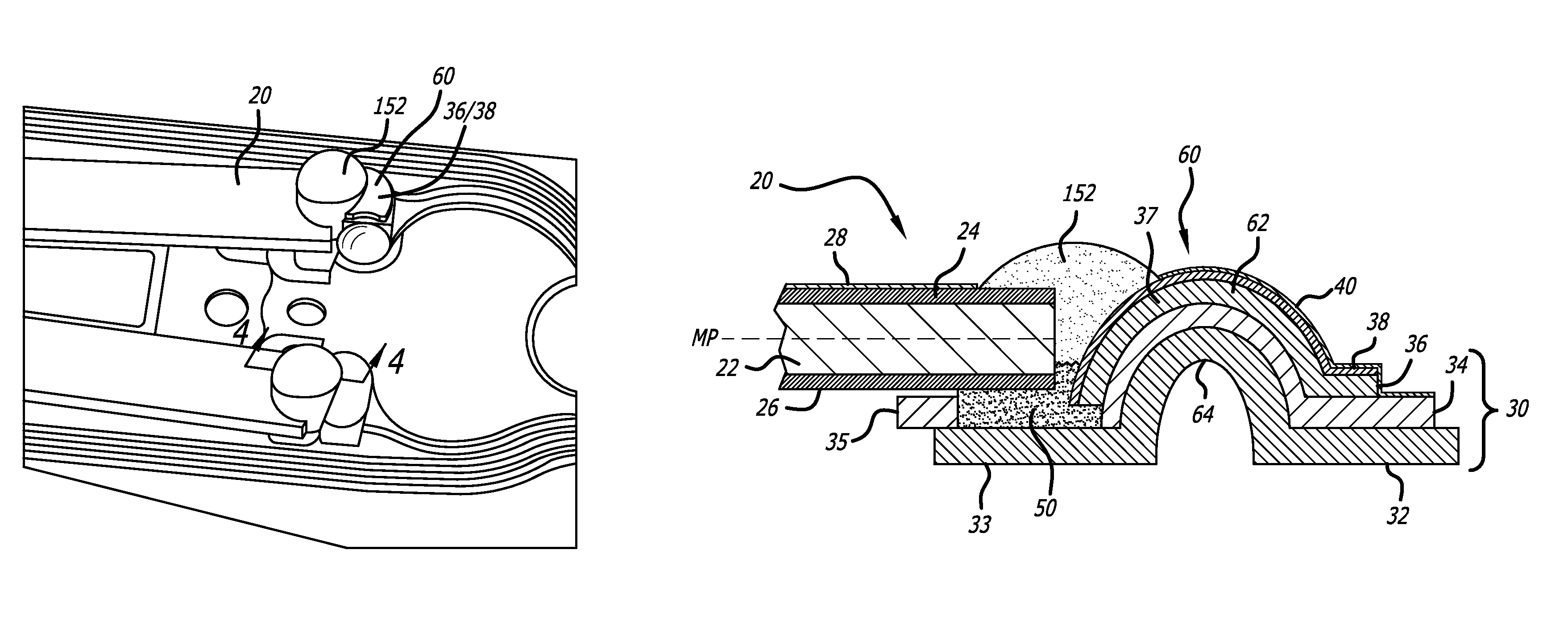
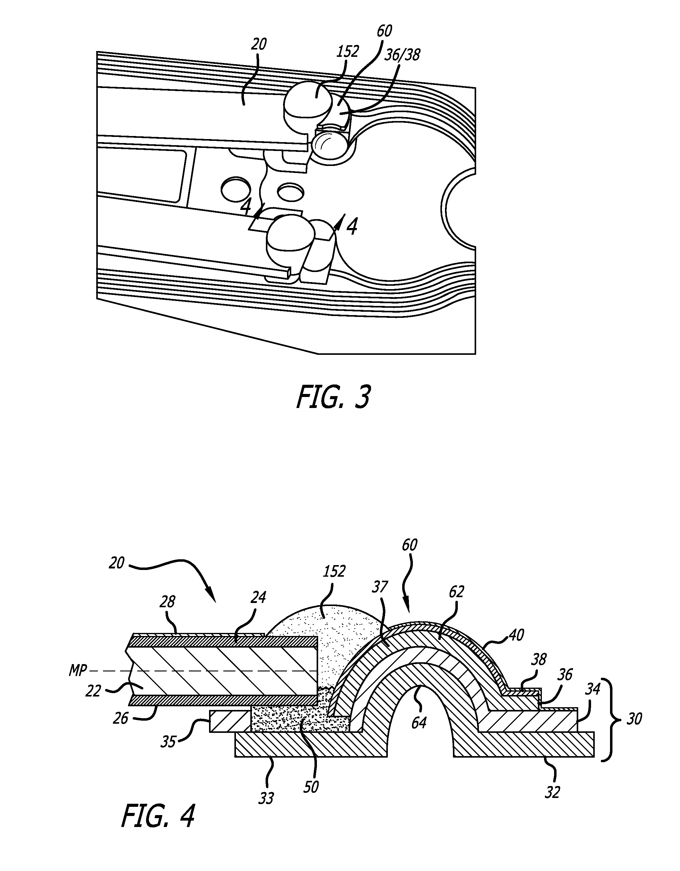
[0017]FIG. 3 is a top perspective view of a PZT connection to an electrical contact pad according to a first illustrative embodiment of the invention, and FIG. 4 is a sectional view thereof taken along section line 4-4. The flexible circuit 30 of the suspension includes a support layer 32 such as a stainless steel (SST) substrate, an insulating layer 34 such as polyimide, and a conductive signal-carrying layer 36 such as copper or copper alloy (generally Cu). Most of the copper layer of the flexible circuit is covered by an insulating coverlay 40 such as polyimide in order to prevent corrosion of the copper and to prevent short circuiting. The copper is covered by a protective metal layer 38 such as nickel followed by gold but is otherwise exposed at an area that defines an electrical contact pad 37 and where an electrical connection to the contact pad is to be made. As used herein and in the claims, the contact pad 37 is “exposed” if it is not covered by an electrical insulator, al...


PUM


Abstract

A flexible electrical circuit such as for use in a hard disk drive dual stage actuated (DSA) suspension has a dimple or other raised feature such as a jog formed in an electrical contact pad. The dimple raises up at least part of the contact pad in height so as to reduce the distance that an electrical bridging component or material such conductive epoxy, solder paste, or jet dispensed solder must traverse in order to complete an electrical connection from the contact pad to an adjacent piezoelectric microactuator or other electrical component for which the electrical circuit carries an electrical signal or electrical power. The reduced distance improves the cleanliness and reliability of the electrical and physical bond, and can allow for electrical connection types that would otherwise be impractical.

Description

CROSS-REFERENCE TO RELATED APPLICATIONS[0001]This application claims priority from U.S. provisional patent application No. 61 / 951,506 dated Mar. 11, 2014.BACKGROUND OF THE INVENTION[0002]1. Field of the Invention[0003]This invention relates to the field of dual stage actuated (DSA) suspensions for disk drives. More particularly, this invention relates to the field of electrical connections to microactuators on DSA suspensions.[0004]2. Description of Related Art[0005]Magnetic hard disk drives and other types of spinning media drives such as optical disk drives are well known. Disk drive suspensions are the assemblies that hold the read / write head over the correct place on the spinning data disk, in order to write data to, and read data from, the desired data track on the disk.[0006]Both single stage actuated disk drive suspensions and dual stage actuated (DSA) suspension are known. In a single stage actuated suspension, only a voice coil motor moves the disk drive suspension. In a DS...

Claims


Application Information

Patent Timeline
IPC IPC(8): G11B5/48H05K3/40
CPCG11B5/4853G11B5/4833G11B5/4846G11B5/4873H05K3/4007G11B5/483H05K1/189H05K2201/10083H05K2203/0323
Inventor HAHN, PETEREE, KUEN CHEEZHANG, LONG
Owner MAGNECOMP
Why Eureka
Try Eureka