Switch driving circuit
a driving circuit and switch technology, applied in the direction of electronic switching, oscillator generator, pulse technique, etc., can solve the problems of high noise interference, precise and rapid transmission of control signals, and strong anti-interference performance, so as to improve anti-interference capability, short transmission time delay, and high stability
- Summary
- Abstract
- Description
- Claims
- Application Information
AI Technical Summary
Benefits of technology
Problems solved by technology
Method used
Image
Examples
first embodiment
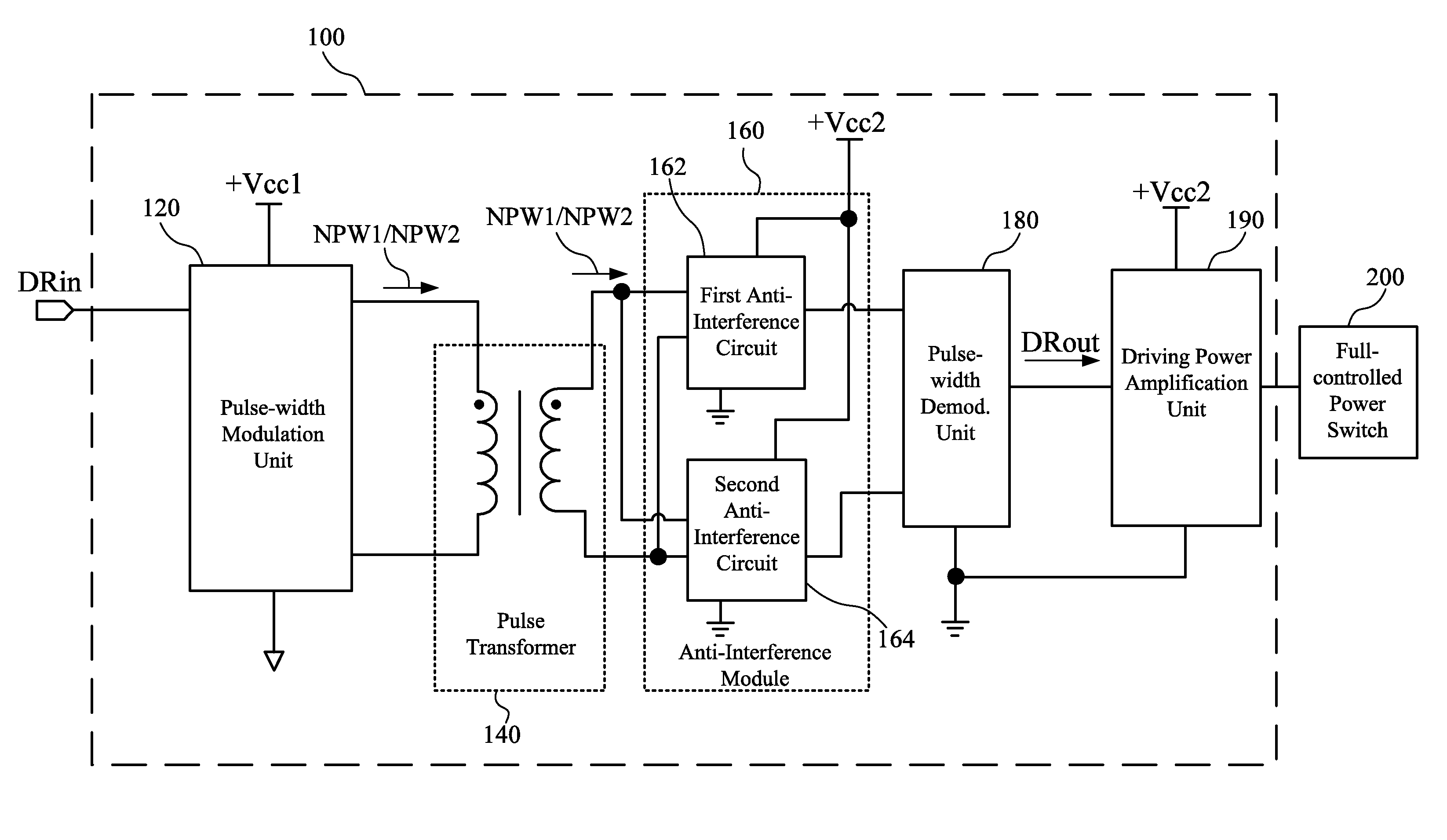
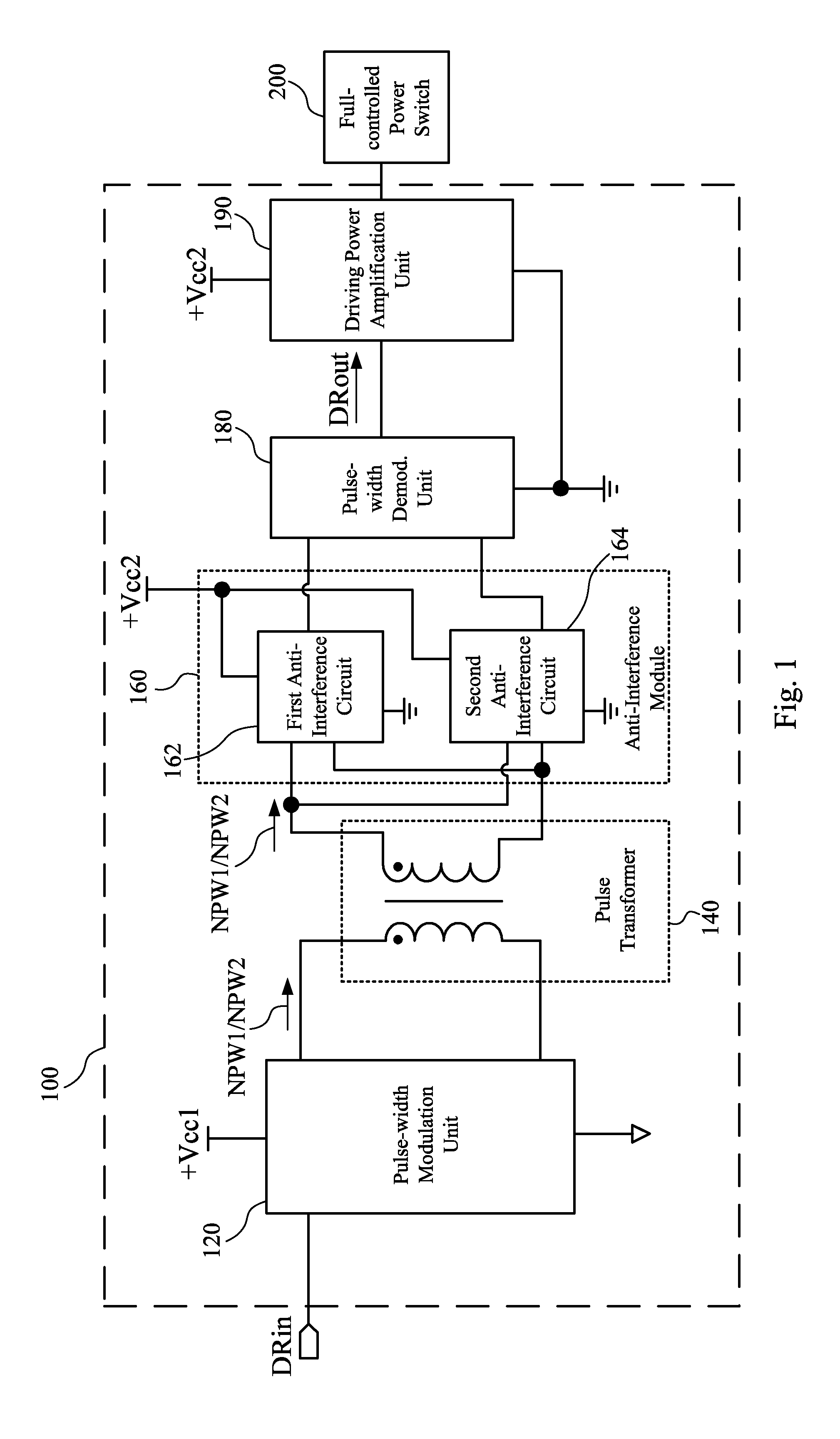
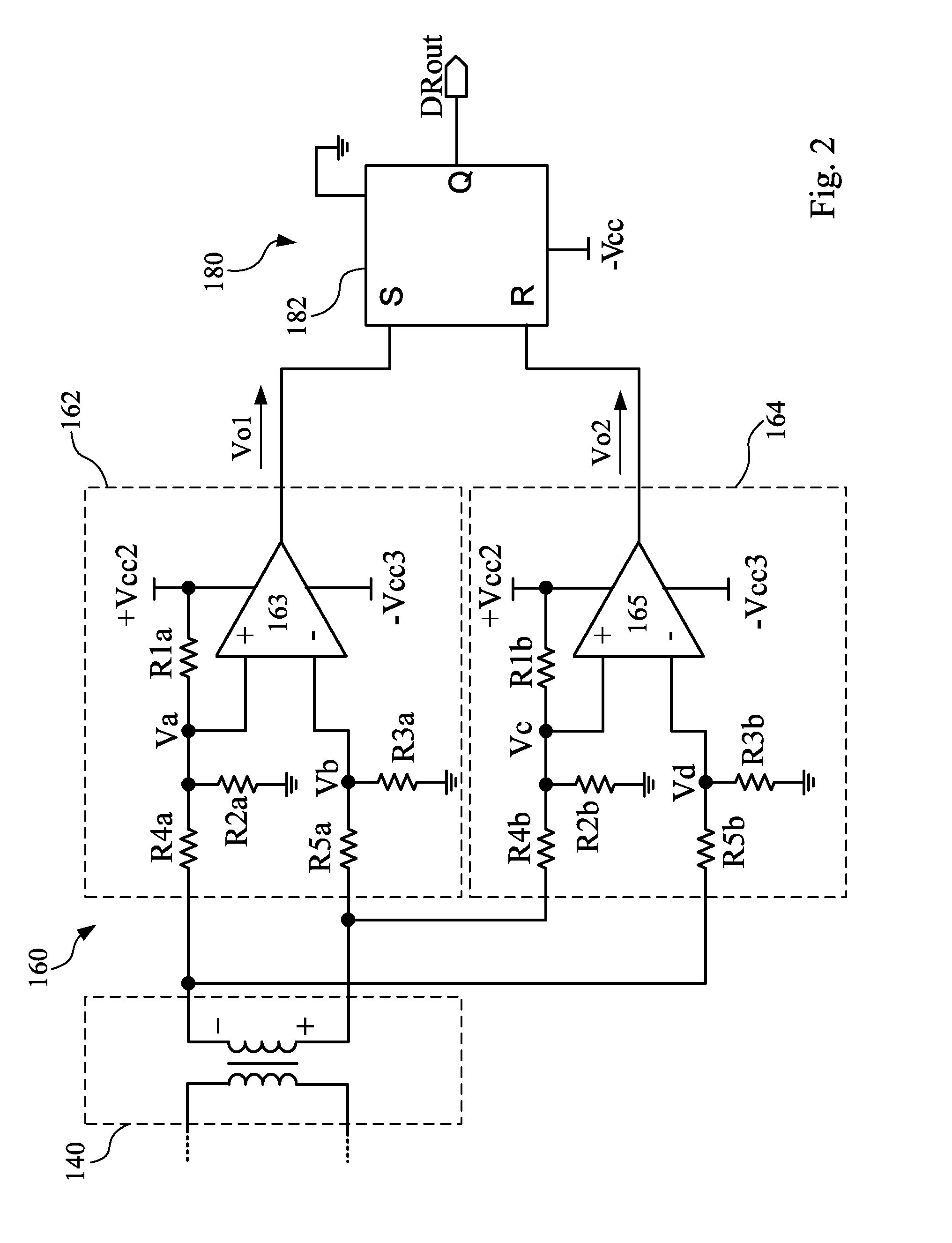
[0035]Referring to FIG. 1, it illustrates a functional block diagram of a switch driving circuit 100 according to the invention. As shown in FIG. 1, the switch driving circuit 100 includes a pulse-width modulation unit 120, a pulse transformer 140, an anti-interference module 160, a pulse-width demodulation unit 180 and a driving-power amplifier 190. The switch driving circuit 100 is coupled to a full-controlled power switch 200. The switch driving circuit 100 receives a driving input signal DRin and converts the driving input signal DRin into a driving output signal DRout. The driving output signal DRout is used for controlling the full-controlled power switch 200. In the embodiments of the invention, the full-controlled power switch 200 may include at least one set of IGBTs.
[0036]The switch driving circuit 100 magnetically isolates the driving input signal DRin from the driving output signal DRout through the pulse transformer 140 so as to avoid the mutual influence between the dr...
second embodiment
[0060]With the development of the semiconductor technology, the feature of the power device switch is improved greatly inevitably. The operation frequency of the power device switch will be very high. At this time, the frequency of the corresponding driving control signal may also be increased. When the driving control signal is an ultra-high frequency driving input signal, the pulse width of the maximum duty ratio (such as Dmax in FIG. 5) corresponding to the ultra-high frequency driving input signal is very small. The magnetic core transmission technology and the same anti-interference circuit also can transfer the ultra-high frequency signal and drive the power device, such as the switch driving circuit 300 in the
[0061]As shown in FIG. 4, according to the second embodiment of the invention, the switch driving circuit 300 includes a signal processing circuit 320, a pulse transformer 340, an anti-interference module 360 and a driving-power amplifier 390. The signal processing circu...
third embodiment
[0068]It should be supplemented that in the third embodiment the anti-interference module 560 has the impedance matching circuit 564. The impedance matching circuit 564 aims to match the impedance of the anti-interference circuit 562. Accordingly, a comparator is not necessary for the impedance matching circuit 564, and the impedance matching circuit 564 only needs to be provided with a corresponding resistor to match with the impedance of the anti-interference circuit 562, such as the first resistor R1b, the second resistor R2b (optional), the third resistor R3b, the fourth resistor R4b and the fifth resistor R5b of the impedance matching circuit 564 in FIG. 7. However, many methods can be used to realize the impedance matching and the invention is not limited to this resistor arrangement method.
[0069]In addition, the structure of the anti-interference circuit in this disclosure is not limited to the anti-interference circuit 162, 164 shown in FIG. 2 or the anti-interference circui...
PUM
 Abstract
Description
Claims
Application Information
 - R&D
- Intellectual Property
- Life Sciences
- Materials
- Tech Scout
- Unparalleled Data Quality
- Higher Quality Content
- 60% Fewer Hallucinations
Browse by: Latest US Patents, China's latest patents, Technical Efficacy Thesaurus, Application Domain, Technology Topic, Popular Technical Reports.
© 2025 PatSnap. All rights reserved.Legal|Privacy policy|Modern Slavery Act Transparency Statement|Sitemap|About US| Contact US: help@patsnap.com


