
Liquid-liquid-liquid three-phase continuous countercurrent extraction device and use thereof

a countercurrent extraction and liquid-liquid technology, applied in the field of extraction and separation, can solve the problems of low selectivity, long separation steps, and the traditional liquid-liquid two-phase extraction technique and the apparatus do not meet the requirements, etc., and achieves convenient operation and control, good processability, and easy scaling up

Inactive Publication Date: 2016-07-26
INST OF PROCESS ENG CHINESE ACAD OF SCI
View PDF11 Cites 0 Cited by
  • Summary
  • Abstract
  • Description
  • Claims
  • Application Information

AI Technical Summary

Benefits of technology

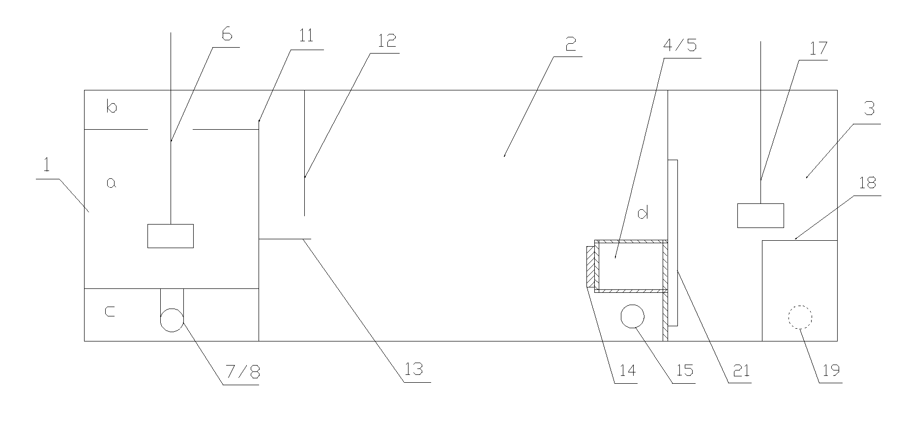
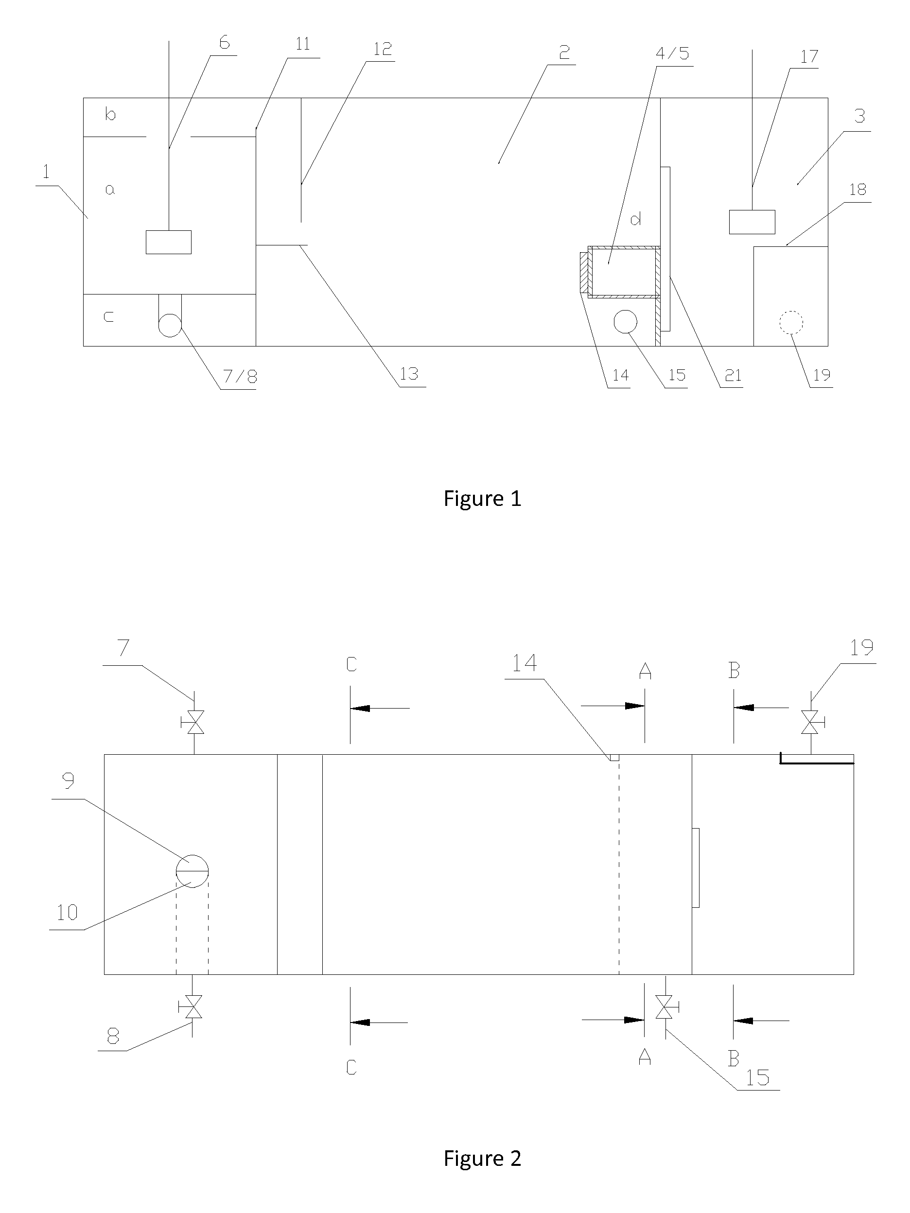
[0008]A vertical return-flow clap-board 12 parallel to the vertical clap-board of the three-phase-mixing chamber 1 is installed on the side of the three-liquid-flow settler 2 that is close to the overflow weir 11. Below the vertical return-flow clap-board, there is a horizontal clap-board 13 perpendicular to the vertical return-flow clap-board connecting to the vertical clap-board of the three-phase mixing chamber. Between the bottom of the vertical return-flow clap-board 12 and the horizontal clap-board 13 under the vertical return-flow clap-board 12, there is an interspace which allows the mixed liquids overflow from the three-phase overflow compartment b to pass through it. The function of the vertical return-flow clap-board 12 and the horizontal clap-board 13 is to decrease the flux of mixed liquids and promote the phase-separation of the mixed three liquid phases overflowed from the three-phase-mixing chamber 1.
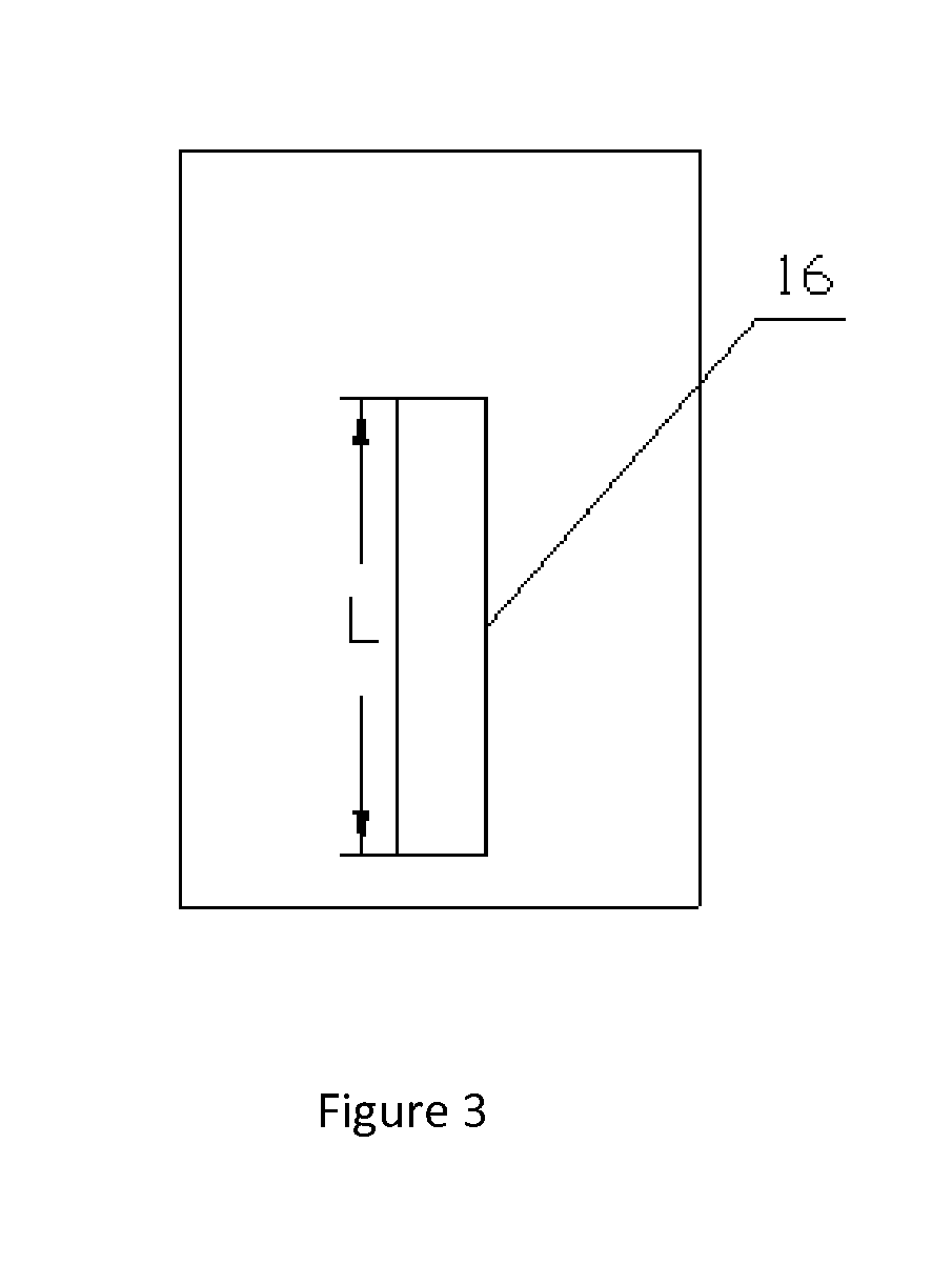
[0011]On the side of the two-phase-mixing chamber 3 that is close to the three-phase liquid flow separator control compartment d in the three-liquid-flow settler 2, at the liquid flow exit 16 on side of the vertical clap-board of the two-phase-mixing chamber 3, there installed a return-flow clap-board 21 parallel to the vertical clap-board with the same width and length as that of the rectangular liquid flow exit 16. There is an interspace between the return-flow clap-board 21 and liquid flow exit 16, which allows the liquid pass across. The purpose of the interspace is: 1) to prevent the return-flow of the mixed liquids in the two-phase-mixing chamber 3 back to the three-liquid-flow settler 2 from the liquid flow exit 16 on side of the vertical clap-board; 2) to allow the liquid flow separated by first control separator 4 or second control separator 5 from the three-phase liquid flow separator control compartment d in the three-liquid-flow settler 2 to flow into the two-phase-mixing chamber 3.
[0015]The apparatus of the present invention has the following advantages:
[0020]5. The apparatus of the present invention is structural concise, convenient to operate and control, good processability, easy to scale-up, and low maintenance and operation cost. It offers a feasible device solution for industrial large-scale applications of using one-step three-phase extraction to extract and separate multi-target in complex system.

Problems solved by technology

With the separation objects and separation systems become increasingly complex, the traditional liquid-liquid two-phase extraction technique and the apparatus do not meet the requirement in emerging chemical separation system.
For some multi-component complex systems and easy emulsifying systems, disadvantages such as low selectivity, lengthy separation steps, and low separation efficiency lie in the traditional liquid-liquid two-phase extraction process, and disadvantages such as complex design of the flow direction and cascade structure, difficulties in effectively controlling of the interphase mass transfer and phase separation processes of the complex system, and high cost in operation and maintenance also lie in the apparatus.
Taking biochemical system separation as an example, the cost in separation steps always constitutes more than 80% in the entire production costs.
The serious lagging in separation apparatus development becomes the bottleneck problem that restricts the progress in our chemical process engineering field.
However, industrial applications of three-phase extraction new techniques are not achieved due to lack of industrial apparatus adapted to three-phase continuous extraction technique.
However, the extraction operation cannot be continuous and the device processing power is limited, not suitable for the industrial continuous production.
However, the flow directions of the three flows in the three-phase system and the countercurrent operations of the three liquid phases cannot be effectively controlled due to the structure design of the tower separation device.
In addition, the mass transfer efficiency and separation parameters are still low, the operating conditions are harsh, flooding and axial backmixing are easy to happen, and scaling-up process is difficult.
The interphase mass transferring is not carried out in a manner of three-liquid-phase process, and the flow behaviors of the three liquid phases are not controllable.
However, this apparatus cannot realize multi-stage continuous and countercurrent extraction operation, the three main phases cannot mix well, and the mass transfer happens only at the phase-to-phase contact surface, with low processability, complicated device structure and difficulties to scale up.
However, this apparatus does not design the device structure from the essential characteristics of the phase formation behavior in the three-phase extraction system.
The extraction and separation operations are based on quick phase separation of the three liquid phases, and the countercurrent operation combinations of any two of the three liquid phases are not realized, thus the process requirement of controlling the mutual mass transfer and distribution among the three liquid phases in the three-phase extraction process are not satisfied.
However, a precondition for this apparatus design is the three liquid flows in the three-phase system can not be miscible during the course of phase-mixing and contacting.
This apparatus cannot realize effective control of the phase formation behavior of the three-phase system consisting of an organic phase, a polymer phase, and a rich brine phase, as well as of the phase type of the dispersion and continuous phases.

Method used


Image

  • Liquid-liquid-liquid three-phase continuous countercurrent extraction device and use thereof
  • Liquid-liquid-liquid three-phase continuous countercurrent extraction device and use thereof
  • Liquid-liquid-liquid three-phase continuous countercurrent extraction device and use thereof

Examples


example 1

Liquid-Liquid-Liquid Three-Phase Extraction and Separation of Pt, Pd and Rh

[0044]The apparatus of the present invention was applied to investigate the effects of one-step extraction and simultaneous three-phase separation of Pt, Pd and Rh in the three-liquid-phase system composed of diisopentyl sulfide-polyethylene glycol-ammonium sulfate-hydrochloric acid aqueous solution of Pt, Pd and Rh three-metal mixtures. The experiment was conducted on Pt, Pd and Rh mixed aqueous solution (Pt, Pd and Rh exist in hydrochloric acid aqueous solutions respectively in the form of aqueous PtCl62−, PdCl42− and RhCl63− ions. The initial total concentrations of Pt, Pd and Rh are 0.52 mmol / L, 0.94 mmol / L and 0.97 mmol / L, respectively). After two groups of three-stage continuous and countercurrent three-phase extraction, the contents of Pt, Pd and Rh were analyzed and determined in the diisopentyl sulfide organic top phase, the polyethylene glycol polymer middle phase, and the ammonium sulfate aqueous b...

example 2

Liquid-Liquid-Liquid Three-Phase Extraction and Separation of Ti, Fe and Mg

[0045]The apparatus of the present invention was applied to investigate the effects of one-step extraction and simultaneous three-phase separation of Ti, Fe and Mg in the three-liquid-phase system composed of P204 (diisooctyl phosphate)-polyethylene glycol-ammonium sulfate-Ti, Fe and Mg mixed aqueous solution. The experiment was conducted on Ti, Fe and Mg mixed aqueous solution from Panzhihua, Sichuan, China (Ti, Fe and Mg exist in aqueous solution of pH=2 as the form of aqueous Ti4+, Fe3+ and Mg2+ ions, respectively. The initial total concentrations of Ti, Fe and Mg are 30 mmol / L, 5 mmol / L, and 15 mmol / L, respectively). After two groups of three-stage continuous and countercurrent three-phase extraction, the contents of Ti, Fe and Mg were analyzed and determined in the P204 organic top phase, the polyethylene glycol polymer middle phase, and the ammonium sulfate aqueous bottom phase, respectively, obtained a...

example 3

Liquid-Liquid-Liquid Three-Phase Extraction and Separation of O-Nitrophenol and P-Nitrophenol Binary Mixture Solution

[0046]The apparatus of the present invention was applied to investigate the effects of one-step extraction and simultaneous three-phase separation of o-nitrophenol and p-nitrophenol in the three-liquid-phase system composed of nonane-polyethylene glycol-ammonium sulfate-o-nitrophenol and p-nitrophenol binary mixture aqueous solution. The experiment was conducted on o-nitrophenol and p-nitrophenol binary mixture aqueous solution (the initial concentrations of o-nitrophenol and p-nitrophenol are both 7.19 mmol / L). After two groups of three-stage continuous and countercurrent three-phase extraction, the contents of o-nitrophenol and p-nitrophenol were analyzed and determined in the nonane organic top phase, the polyethylene glycol polymer middle phase, and the ammonium sulfate aqueous bottom phase, respectively, obtained after separation by the three-phase liquid flow co...


PUM

PropertyMeasurementUnit
speedaaaaaaaaaa
heightaaaaaaaaaa
widthaaaaaaaaaa

Abstract

A liquid-liquid-liquid three-phase continuous and countercurrent extraction apparatus comprises a three-phase-mixing chamber, a three-liquid-flow settler, and a two-phase-mixing chamber; a liquid-flow control separator placed in the three-liquid-flow settler aims to flexibly regulate the directions of three liquid flows in the three-phase system by different control separator combinations to achieve either a countercurrent operation of the top-layered phase with the middle-bottom two-layered mixtures, or a countercurrent operation of the top-middle two-layered mixtures with the bottom-layered phase; and a method of using the same, relating to extraction and separation field of chemical technology.

Description

FIELD OF THE INVENTION[0001]The present invention relates to extraction and separation field of chemical technology, and in particular, to an apparatus for liquid-liquid-liquid three-phase continuous and countercurrent extraction and the method of using the same, in order to realize three-phase extraction and simultaneous three-liquid-phase separation of multiple target components in complex systems.BACKGROUND OF THE INVENTION[0002]Extraction is an important chemical separation technique, possessing advantages such as high target selectivity, good adaptability to various materials, low energy consumption, easy to operate, and easy to achieve large-scale continuous production. Extraction can be widely used in chemical industry, metallurgy, new energy field, bio- and medical engineering, environmental engineering, natural product extraction, preparation of new materials and the efficient utilization of resources, etc., thus is known as “the most promising green chemical separation tec...

Claims


Application Information

Patent Timeline
Patent Type & Authority Patents(United States)
IPC IPC(8): B01D11/04C02F3/12
CPCB01D11/0446B01D11/0457C02F3/121
Inventor LIU, HUIZHOUHUANG, KUNAN, ZHENTAO
Owner INST OF PROCESS ENG CHINESE ACAD OF SCI
Learn More