
Catalysts for carbon dioxide reforming of hydrocarbons

a hydrocarbon and catalyst technology, applied in the direction of physical/chemical process catalysts, metal/metal-oxide/metal-hydroxide catalysts, etc., can solve the problems of catalyst coking, catalyst degradation via catalyst coking, clogging of catalyst pores, etc., and achieve the effect of increasing reaction efficiency

Active Publication Date: 2016-11-22
SAMSUNG ELECTRONICS CO LTD
View PDF56 Cites 2 Cited by
  • Summary
  • Abstract
  • Description
  • Claims
  • Application Information

AI Technical Summary

Benefits of technology

The catalyst exhibits reduced carbon deposition and sintering, maintaining high reaction efficiency and durability, with a carbon deposition rate less than 0.1% and minimal change in particle size over 200 hours at 700° C. to 900° C., enhancing the stability and performance of the CO2 reforming process.

Problems solved by technology

One of the major problems occurring in such reactions is catalyst degradation via catalyst coking, for example represented by the following reaction schemes.
Such reactions cause the generation of carbon, which is then deposited onto the catalyst, leading to a decrease in a reaction surface area, clogging of the pores in the catalyst, and acceleration of the support degradation.
As a result, the catalyst eventually loses its activity.
Due to the sintering phenomenon, a thermally unstable catalyst tends to aggregate to grow into a relatively large particle when it is subjected to a relatively high temperature reaction.
Accordingly, the sintering may lead to a smaller area of the catalytically active surface and make it more difficult for the reaction gas to diffuse into the catalytically active site.
Moreover, the sintering may cause a decreased interface between the catalyst and the support and thus may weaken the bonding strength therebetween.
As a result, the conversion rate of the reaction gas becomes lower, the internal pressure of a reactor increases, and the durability of the catalyst / support is deteriorated.

Method used


Image

  • Catalysts for carbon dioxide reforming of hydrocarbons
  • Catalysts for carbon dioxide reforming of hydrocarbons
  • Catalysts for carbon dioxide reforming of hydrocarbons

Examples


example

Preparation of a Catalyst

Example 1

Preparation of a Catalyst Including NiCoMg Solid Solution Particles Supported onto Al2O3

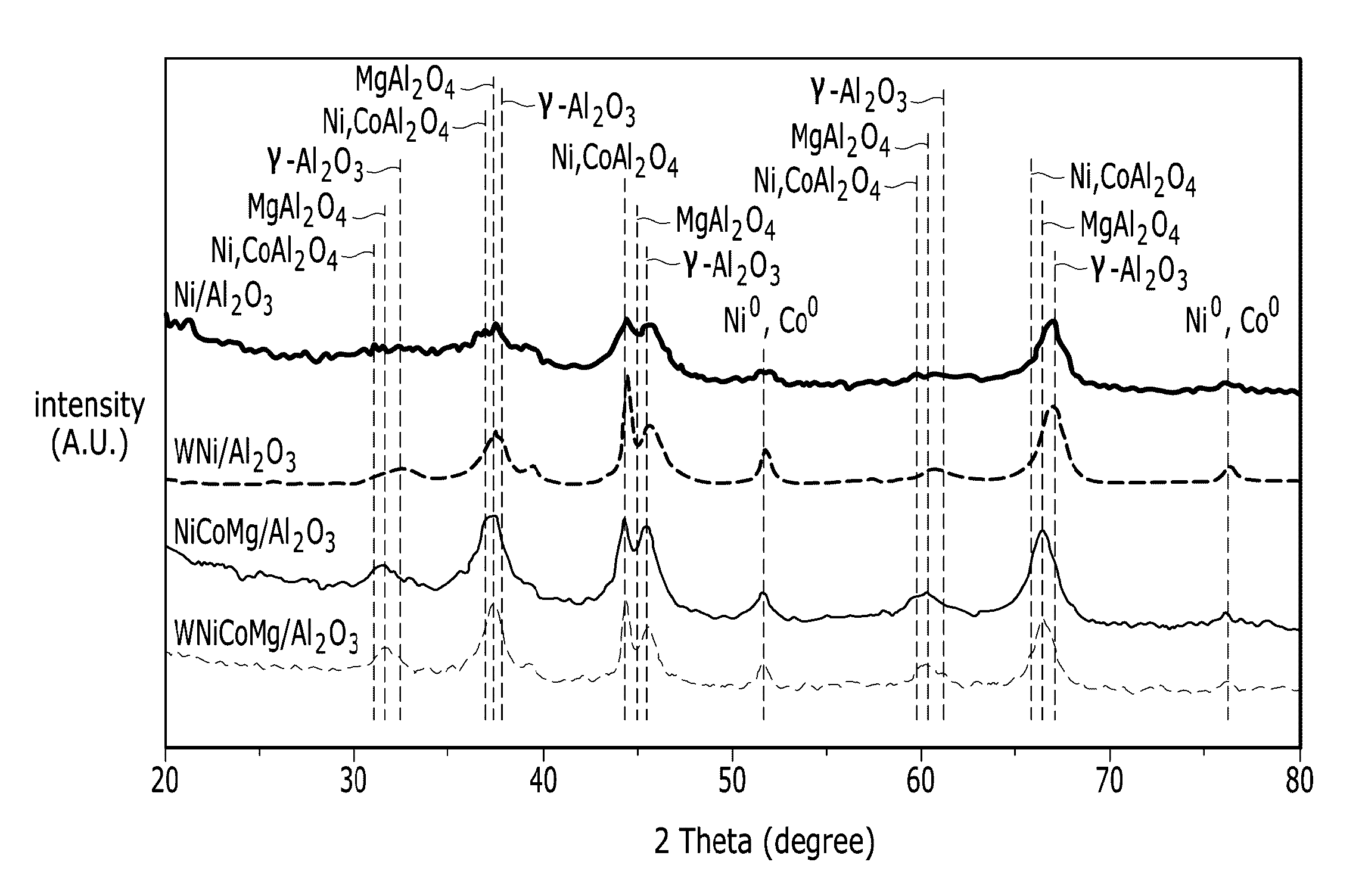
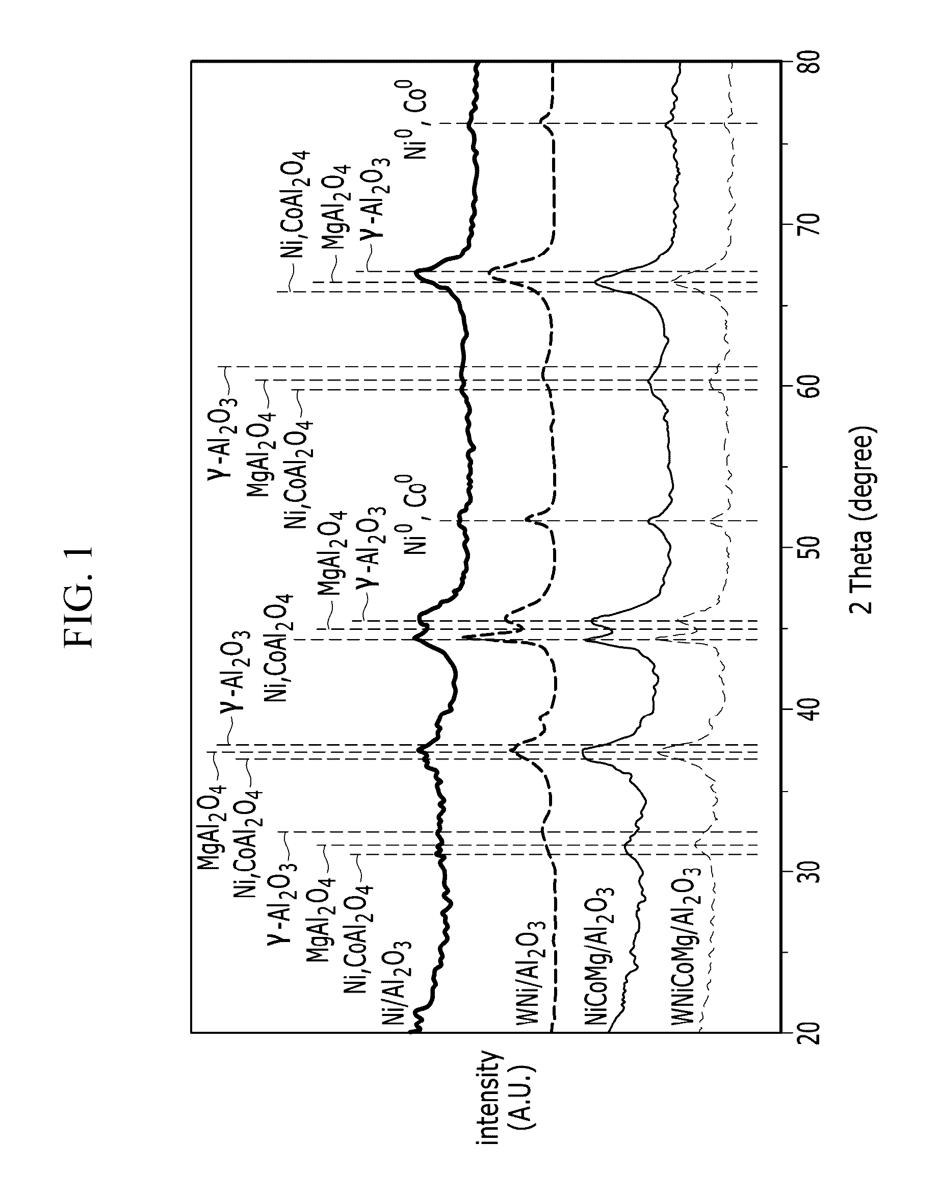
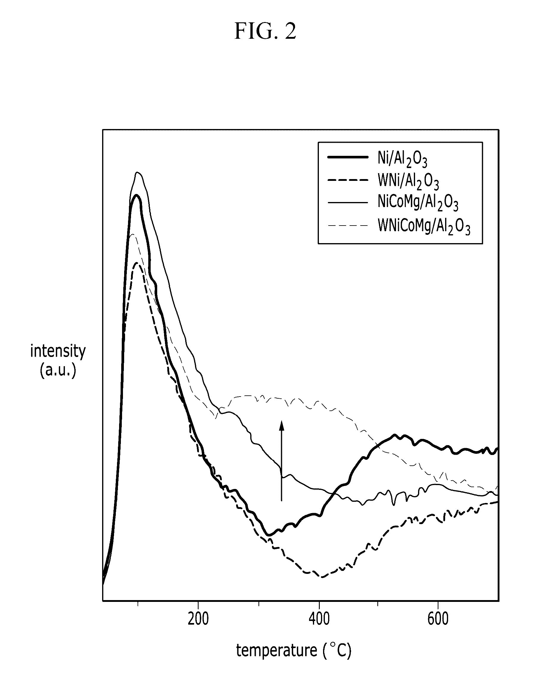
[0076]Ni(NO3)2-6H2O, Mg(NO3)2-6H2O, and Co(NO3)2-6H2O are put into 5 ml of deionized water while stirring and completely dissolved therein to produce an aqueous solution of the metal salts. Using the aqueous solution of the metal salts and via the incipient wetness impregnation method, 10 g of gamma alumina (from Aldrich, specific surface area: 150 m2 / g, granule diameter: about 3 mmφ, pore volume: 3 to 5 (cm3 / g)m) is co-impregnated with Ni(NO3)2-6H2O, Mg(NO3)2-6H2O, and Co(NO3)2-6H2O. The obtained product is dried in an oven at 120° C. for 24 hours, and calcined in air (300 ml / minute) at 500° C. for 5 hours. The calcined product (i.e., the catalyst) is subjected to a reducing process in a pure H2 atmosphere by increasing a temperature at a rate of 10° C. / min and maintaining the temperature at 850° C. for 2 hours to prepare a catalyst including NiCoMg solid soluti...

example 2

Preparation of a Catalyst Including NiCoMg Solid Solution Particles with Al2O3 Islands Formed Thereon (the Water-Pretreated Catalyst)

[0077]The temperature of the reactor having the catalyst obtained in accordance with Example 1 is decreased to 30° C., and 5 ml of water is added thereto. Then, the reactor is heated at a rate of 10° C. / min to evaporate water in a hydrogen atmosphere, and the catalyst contained therein is heat-treated at 850° C. for one hour to prepare a catalyst wherein the NiCoMg solid solution particle is supported on the alumina support and the solid solution particle includes alumina islands on its surface (hereinafter referred to as WNiCoMg / Al2O3). The amount of Ni, the amount of Co, and the amount of Mg are 3 wt %, 3 wt %, and 3 wt %, respectively, based on the total weight of the catalyst.

experimental example 1

Measurement of BET Surface Area of the Catalyst Prior to and after the Reforming Reaction

[0082]BET surface areas of the catalysts prepared in Examples 1 and 2 are measured using a nitrogen adsorption technology at −196° C. with BELsorp (BEL, Japan) before and after the catalysts are subjected to the reforming reaction. The results are summarized in Table 1. The average particle sizes of the catalyst metal are measured using XRD, TEM, and H2 chemisorption, and the results are compiled in Table 1. Prior to the adsorption measurement, the samples are degassed at a temperature of 200° C. for 24 hours. The CO2 reforming reaction is carried out under the following conditions.

T=850° C., CH4:CO2:N2=1.0:1.0:1.0, 200 hr, GHSV=10 k h−1

[0083]

TABLE 1BET surface areaAverage particle sizeCatalyst(m2 / g)(nm)Fresh NiCoMg / Al2O3167.3011Used NiCoMg / Al2O101.7715Fresh WNiCoMg / Al2O3111.7614Used WNiCoMg / Al2O398.6216

[0084]The results of Table 1 confirm that the catalyst of Example 1 exhibits a relatively sma...


PUM

PropertyMeasurementUnit
sizeaaaaaaaaaa
specific surface areaaaaaaaaaaa
temperatureaaaaaaaaaa

Abstract

A catalyst for reforming hydrocarbons may include an inorganic oxide and a catalyst metal supported on the inorganic metal oxide. At least a portion of the catalyst metal may be supported in the form of a solid-solution particle. The catalyst metal may include a first metal (selected from cobalt, iron, copper, and manganese); nickel; and magnesium.

Description

CROSS-REFERENCE TO RELATED APPLICATION[0001]This application claims priority under 35 U.S.C. §119 to Korean Patent Application No. 10-2013-0038803, filed in the Korean Intellectual Property Office on Apr. 9, 2013, the entire contents of which are incorporated herein by reference.BACKGROUND[0002]1. Field[0003]The present disclosure relates to a catalyst for CO2 reforming of hydrocarbons, a method of manufacturing the same, and a hydrocarbon reforming process using the same.[0004]2. Description of the Related Art[0005]Hydrocarbons, such as natural gas and petroleum gas, may be reformed in the presence of a reforming material (e.g., carbon dioxide, water vapor, and oxygen) and a catalyst. For example, methane in natural gas may produce gases such as hydrogen and carbon monoxide via a carbon dioxide reforming (CDR) reaction represented by the following Reaction Schemes.CH4+CO2→2CO+2H2 [ΔHo=247.3 kJ / mol]  (1)CO2+H2→CO+2H2O [ΔHo=41 kJ / mol]  (2)[0006]Such reactions are endothermic and requ...

Claims


Application Information

Patent Timeline
Patent Type & Authority Patents(United States)
IPC IPC(8): C01B3/38B01J23/78C01B3/40B01J37/08B01J37/18B01J21/04B01J35/00B01J35/10
CPCB01J23/78B01J21/04B01J35/002B01J35/006B01J35/0013B01J35/1019B01J37/08B01J37/18C01B3/40C01B2203/0238C01B2203/1047C01B2203/1052C01B2203/1058C01B2203/1076C01B2203/1082C01B2203/1094C01B2203/1241Y02P20/52B01J35/393B01J35/615B01J35/45B01J2235/00B01J2235/10B01J2235/30B01J2235/15B01J23/75B01J23/34B01J6/00B01J35/23B01J35/30
Inventor SON, IN HYUKLEE, SEUNG JAE
Owner SAMSUNG ELECTRONICS CO LTD
Learn More