Paranasal sinus access implant devices and related tools, methods and kits

a technology for accessing implants and paranasal sinuses, which is applied in the field of paranasal sinus conditions, can solve problems such as the difficulty of insertion of conduits into fistulas for implantation, and achieve the effect of preventing lateral deformation of implant devices

Active Publication Date: 2017-02-07
SINOPSYS SURGICAL
View PDF136 Cites 6 Cited by
  • Summary
  • Abstract
  • Description
  • Claims
  • Application Information

AI Technical Summary

Benefits of technology

[0009]It has been found that implant devices may be better retained following implantation if the implant devices include anchoring surface features including protrusion areas and recess areas along a conduit that is to be inserted into the fistula for implantation. Anchoring is enhanced when a maximum outside diameter defined by protrusion areas to be disposed in the fistula is larger than the diameter of the fistula that was formed to accept the conduit of the implant device. This creates a snug fit of the conduit in the fistula, with tissue forcing itself into the recess areas of the anchoring surface feature. However, such implantation conduits made of relatively flexible plastic materials may bunch up, such as in the manner of an accordion, making it difficult to insert the conduit into the fistula for implantation. It has been found that by including a thicker conduit wall in a proximal portion of the conduit of an implant device than is included in a distal portion that is inserted first into the fistula, that the ease of insertion of the conduit may be significantly improved. In addition, a thicker conduit wall in a proximal portion of the conduit provides added mechanical durability of the conduit adjacent the proximal end of the implant device and reducing potential for mechanical damage to proximal portions of the conduit due to mechanical interactions that may occur between the implant device and tools used during an implantation procedure or during performance of medical treatments and other procedures following implantation.
[0060]Forming a fistula for implantation of an implant device to provide a fluid passage between the lacrimal apparatus and a paranasal sinus involves making a hole through a wall of the bone in which the cavity of the paranasal sinus is located. As described herein, such a hole may be made by a sytlet or other solid piercing instrument and then widened as needed to form the fistula to the desired size for implantation of the implant device. For example following the initial piercing to make an initial hole, the hole may be dilated using dilators to make the hole progressively larger until the desired size is obtained. However, it has been found that when forming a fistula for implantation in such a manner, the bone tends to crack and shatter in the vicinity of hole. Although this does not present a medical problem, it has been found that if the bone is kept more in-tact in the vicinity of the hole, then the bone may provide mechanical support to help secure the implant device in place and prevent the implant device from migrating out of the fistula following implantation. Bone integrity in the vicinity of the fistula may be improved by cutting the hole for the fistula rather than piercing and dilating the hole. By cutting through the bone, rather than pushing through the bone, the bone remains more in-tact in the vicinity of the hole and provides better mechanical support to help retain the implant device in place in the fistula following implantation. The implantation kit of the second aspect may include tools useful for cutting a hole for a fistula and implanting an implant device.
[0067]A kit may include a carrier tool, also referred to as an implantation tool, for carrying the implant device during an implantation procedure. Such a carrier tool may include a carrier member with a distal tip, with the carrier member being adapted to be disposed through a fistula between the lacrimal apparatus in the orbit and a paranasal cavity with the distal tip located in the paranasal cavity. The carrier tool may include a hand-manipulable handle connected to the carrier member. An implant device may be mountable on the carrier member for implantation of the implant device, with the mounted implant device disposed between the handle and the distal tip with the carrier member disposed through the internal passage and with a proximal end of the implant device disposed toward the handle and a distal end of the implant device disposed toward the distal tip of the member. When the implant device is mounted for implantation, the carrier member, and the carrier tool, may be disengageable from the implant device for implantation of the implant device during an implantation procedure to provide fluid access to a paranasal sinus. A clearance fit of the carrier member in the internal passage of the implant device when the implant device is mounted on the carrier member for implant placement may be small to ensure a close fit and help prevent lateral deformation of the implant device during implantation. For example such a clearance fit may be no larger than 0.5 millimeter, no larger than 0.4 millimeter, no larger than 0.3 millimeter, no larger than 0.2 millimeter or no larger than 0.1 millimeter. Having a close fit between of the carrier member in the internal passage of the implant device helps prevent accordion-like bunching of the implant device during an implant procedure as the carrier tool with the mounted device may be advanced to advance (push) the carrier member and the mounted implant device into the fistula for implantation.

Problems solved by technology

Such paranasal sinus access implant devices have significant potential for performance of medical procedures and treatments of paranasal sinuses, but such potential has not yet been realized, and there is a continued need for implant devices and accompanying procedures that facilitate easy and effective implantation with good anchoring of the implant device, patient comfort, implant device durability post implantation and effective performance of medical procedures.
However, such implantation conduits made of relatively flexible plastic materials may bunch up, such as in the manner of an accordion, making it difficult to insert the conduit into the fistula for implantation.

Method used


Image

  • Paranasal sinus access implant devices and related tools, methods and kits
  • Paranasal sinus access implant devices and related tools, methods and kits
  • Paranasal sinus access implant devices and related tools, methods and kits

Examples


Embodiment Construction

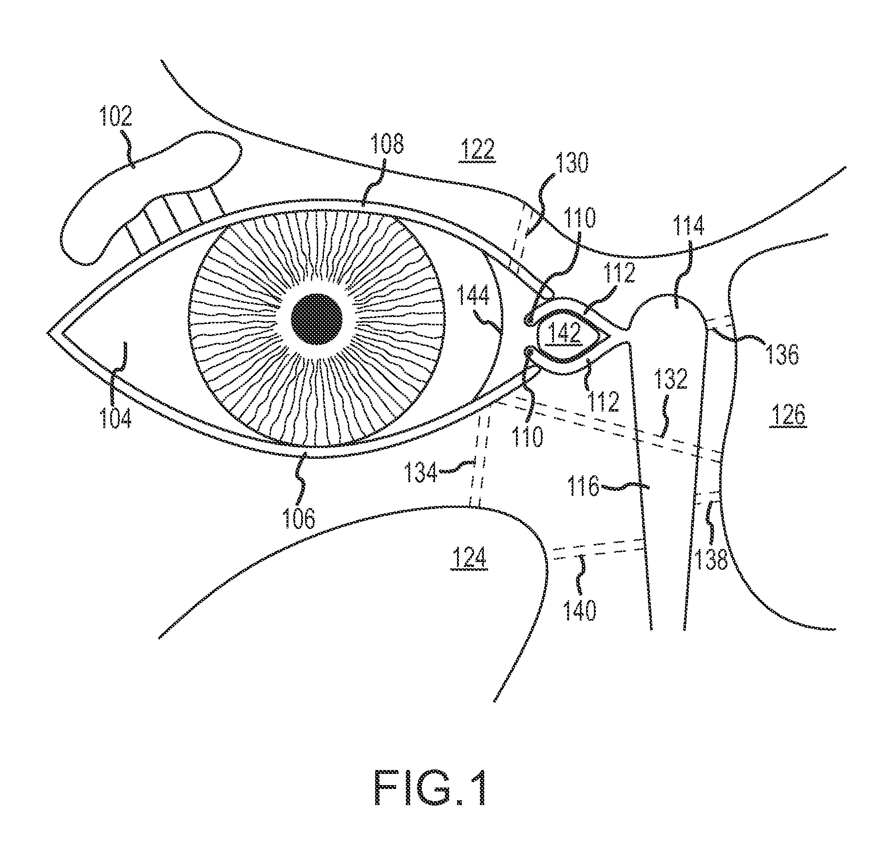
[0115]The terms “lacrimal apparatus” and “lacrimal system” are used interchangeably herein to refer to the collection of physiological components that accomplish the production and secretion of lacrimal fluid to lubricate the eyeball, containment of lacrimal fluid in a reservoir of lacrimal fluid in the orbit and drainage of lacrimal fluid from the orbit to the nasal cavity. The lacrimal apparatus includes the lacrimal glands, the tear drainage system and the reservoir of lacrimal fluid located between the lacrimal glands and the tear drainage system. The reservoir of lacrimal fluid includes the eyelid margins and the conjunctival sac (and including the pool of tears in the lower conjunctival cul-de-sac that is sometimes referred to as the lacrimal lake). The tear drainage system includes the puncta, canaliculi and nasolacrimal duct (including the so-called lacrimal sac located at the top of the nasolacrimal duct) through which excess tears drain to Hasner's valve and into the nasal...


PUM


Abstract

A paranasal sinus access implant device to provide an artificial fluid path in fluid communication with the lacrimal apparatus may be implanted through a fistula opening into the lacrimal apparatus. The implant device may have a conduit with a first longitudinal portion having a larger minimum wall thickness than a minimum wall thickness of a second a second longitudinal portion of the conduit located distal of the first longitudinal portion. Various kits may include a paranasal sinus access implant device and one of more other components for a procedure involving implantation. A method involves use of a cutting tool to cut away tissue to prepare a fistula sized for implantation.

Description

CROSS-REFERENCE TO RELATED APPLICATIONS[0001]This application claims the benefit of U.S. provisional patent application no. 61 / 757,046 entitled “IMPLANT DEVICE, METHOD AND KIT FOR IMPLANTATION BETWEEN THE LACRIMAL SYSTEM AND A PARANASAL SINUS” filed Jan. 25, 2013 and the benefit of U.S. provisional patent application No. 61 / 891,250 entitled “PARANASAL SINUS ACCESS IMPLANT DEVICES AND RELATED TOOLS, METHODS AND KITS” filed Oct. 15, 2013, the entire contents of each of which is incorporated by reference herein.[0002]This application incorporates by reference each and every portion of the following: international patent application no. PCT / US2011 / 055456 entitled “IMPLANT DEVICE, TOOL, AND METHODS RELATING TO TREATMENT OF PARANASAL SINUSES” filed Oct. 7, 2011; U.S. nonprovisional patent application Ser. No. 13 / 225,213 entitled “IMPLANT DEVICE, TOOL, AND METHODS RELATING TO TREATMENT OF PARANASAL SINUSES” filed Sep. 2, 2011; U.S. provisional patent application No. 61 / 528,058 entitled “IM...

Claims


Application Information

Patent Timeline
Patent Type & Authority Patents(United States)
IPC IPC(8): A61M5/00A61F9/007A61M27/00A61K9/00A61B17/24A61M29/02
CPCA61M27/002A61F9/00772A61B17/24A61K9/0051A61M29/02A61M3/0233A61B17/11A61M31/00A61M2210/0681
Inventor WILLOUGHBY, BRIAN JAMESOLIVER, CHRISTOPHER LEEROSS, HARRYCIMINO, WILLIAM W.
Owner SINOPSYS SURGICAL
Why Eureka
Try Eureka