Tool grinder

a tool grinder and grinder technology, applied in the field of tool grinders or sharpeners, can solve the problems of more aggressive geometry of contemporary tools, more difficult reconditioning, and more expensive than regular high-speed steel cutters, and achieve the effect of easy reproduction of tool geometry

Active Publication Date: 2017-03-14
TOYCEN JEFF
View PDF11 Cites 0 Cited by
  • Summary
  • Abstract
  • Description
  • Claims
  • Application Information

AI Technical Summary

Benefits of technology

[0010]An object of the present invention is to overcome at least one of the shortcomings of the prior art by providing a tool grinder able to easily reproduce tool geometry, preferably cutter end geometry, most preferably without heat damage to the tool.
[0011]Accordingly, the present invention relates to a tool grinding device and rotating cutting tool sharpening device comprising a base, a tool spindle assembly which supports a tool or rotatary cutting tool, and enables reciprocation in a first direction parallel to the base and a motor tower assembly which supports a motor for rotating a grinding or sharpening wheel and enables reciprocation along a second axis parallel to the base. The motor tower assembly further enables rotation of the motor about a vertical axis intersecting with the motor axis. The motor tower assembly also enables tilting of the motor axis relative to horizontal about a tilt axis perpendicular to the motor axis, for maximum versatility in orientation of the wheel relative to the tool. The tower assembly is movable between a first position, wherein an end face of the wheel is parallel to the tool axis and vertical or at different angles from vertical, and a second position wherein the end face is perpendicular to the tool axis and vertical or at different angles from vertical so that the end face of the wheel faces an axial end face of the tool in the second position or is positioned beside the tool behind the axial end face.

Problems solved by technology

Moreover, contemporary tools have more aggressive geometry, are more expensive than regular high-speed steel cutters, and are more difficult to recondition.
The binder breaks down over time due to cycling of load moments, causing the leaching of the cobalt away from the carbide powder.
This leads to localized degradation of the integrity of the substrate to such a degree that the area of the end mill cutter tool that was under the highest loads should not be returned to service as the material has been altered at the inter-granular level.
Re-inspection slows down the manufacturing / shop process and is therefore unwelcome.
Also, the end mill cutter tool that has just been returned to service generally does not perform as well as or as long as a new one.
However, careless reconditioning can result in disproportionately maintained clearance angles and flute geometry, affecting friction and chip evacuation and causing a reduction in performance.
In small carbide milling cutters, the area of high exposure to heat, load and friction is a “throw away” or for one time use, due to material breakdown.
In general, shops do not use reconditioned tools because they are usually small and associated with too many issues, which affect the true reconditioning cost.

Method used


Image

  • Tool grinder
  • Tool grinder
  • Tool grinder

Examples


Embodiment Construction

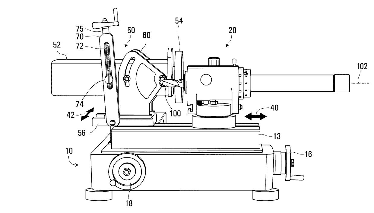
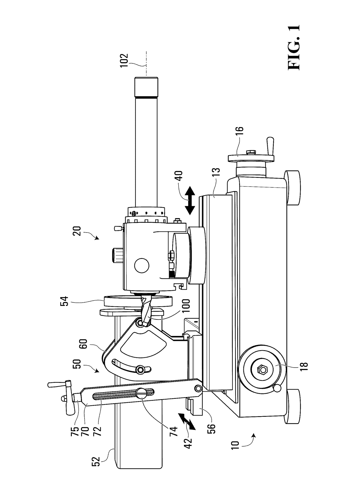
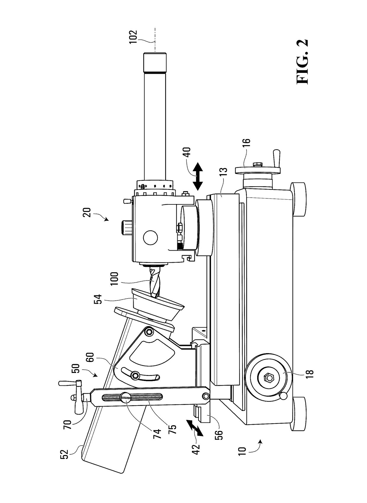
[0030]An exemplary device in accordance with the invention for the grinding or sharpening a tool, for example a rotating cutting tool, is illustrated in the attached drawings and the principle construction of an exemplary embodiment of the device will be discussed in the following with reference to FIGS. 1 to 9. The exemplary embodiment described is an end mill cutter sharpening device.

[0031]The end-mill (or any other kind of rotating cutting tool) sharpening device in accordance with the present invention, has improved face grinding capabilities as compared to conventional grinding tools, provides a better opportunity for elaborate feature reproduction and includes a very stable sharpening wheel mounting for the achievement of improved surface finishes.

[0032]As is apparent from FIGS. 1 to 3, the principle parts of the device of the invention include a main base 10, preferably a ground stone base for rigidity and harmonic stability, a multi-axis tool spindle assembly 20 and a multi-...


PUM

PropertyMeasurementUnit
anglesaaaaaaaaaa
angleaaaaaaaaaa
rotationaaaaaaaaaa

Abstract

The end mill grinding device of the present invention includes a tool spindle assembly and a motor tower which enables multi-axis positioning of a sharpening wheel in relation to an end mill cutting tool being sharpened, for sharpening the end mill tool. The present invention combines linear sharpening and radial tool end grinding capability in the same device.

Description

[0001]This application claims the benefit of priority of U.S. Provisional Patent Application No. 62 / 049,425 filed Sep. 12, 2014, the content of which is incorporated herein by reference.TECHNICAL FIELD[0002]The present invention relates to a machine shop grinder or sharpener, for example a bench-top end mill sharpener.BACKGROUND OF THE INVENTION[0003]Machine shops universally use end mills in computerized milling machines, e.g. computer numerical control (CNC) milling machines, as a cutting tool for all industrial milling applications, such as profile milling, tracer milling, face milling, and plunging. End mills are categorized by the number of flutes, the helix angle, the material and the coating material. Over the last two decades the speed of CNC milling machines has increased ten fold, requiring the use of milling cutters with exotic coatings or made from solid carbide to improve part cycle time and tool life. Moreover, contemporary tools have more aggressive geometry, are more...

Claims


Application Information

Patent Timeline
Patent Type & Authority Patents(United States)
IPC IPC(8): B24B3/00B24B3/06B24B41/02B24B41/06
CPCB24B3/06B24B41/02B24B41/066
Inventor TOYCEN, JEFF
Owner TOYCEN JEFF
Why Eureka
Try Eureka