X-ray surface analysis and measurement apparatus

a measurement apparatus and surface technology, applied in the direction of x-ray tube target materials, instruments, x-ray tube targets and convertors, etc., can solve the problems of inability to achieve beamtime, inability to use conventional laboratory equipment, and inability to obtain beamtime in months, so as to achieve wide choice of x-ray energy, increase brightness, and high x-ray brightness

Inactive Publication Date: 2017-03-14
SIGRAY INC
View PDF223 Cites 66 Cited by
  • Summary
  • Abstract
  • Description
  • Claims
  • Application Information

AI Technical Summary

Benefits of technology

[0012]The present invention discloses an x-ray surface analysis and characterization apparatus that comprises a novel x-ray source using the linear accumulating of x-rays that provides high x-ray brightness and a wide choice of x-ray energy. The linear accumulation x-ray source compromises two or more sub-sources of x-rays, with each sub-source having predetermined x-ray spectral characteristics, with the sub-sources separated physically from each other by predetermined spatial intervals and aligned with each other along a predetermined axis to allow accumulation of x-rays along that axis, thereby increasing brightness. The x-ray sub-sources produce x-rays by electron bombardment of a target, and the linear accumulation of x-rays from the multiple origins leads to greater x-ray brightness.
[0014]A significant advantage to some embodiments is that the high x-ray brightness from the linearly accumulating source results in greatly improved throughput and higher sensitivity for the above mentioned grazing incidence x-ray techniques, which is particularly important for industrial applications such as semiconductor metrology. Furthermore, the higher brightness combined with a wider range of characteristic x-rays can improve elemental and analytical sensitivity for TXRF and extend the analytical performance capabilities of XRR, TXRF, GIXRD, GID, and GISAXS.
[0016]Additional advantages may be provided in some embodiments of the invention by using an axially symmetric x-ray optic with a large numerical aperture, producing a higher brightness x-ray beam incident upon the sample. Additional advantages may be provided in some embodiments of the invention by using optics of small point spread function and using a flat crystal monochromators within the optical train to provide higher spatial resolution and analytical sensitivity.

Problems solved by technology

However, these facilities are large, often occupying acres of land, and expensive to operate, and obtaining beamtime can take months of waiting.
They are impractical for conventional laboratory use.
Until now, laboratory application of the grazing incidence x-ray techniques described above have relied on conventional laboratory x-ray sources that use an extended solid metal anode (such as copper) and have relatively low brightness and limited choice of x-ray spectra of the incident x-ray beam, due to limitation of the x-ray target anode materials with suitable thermal, mechanical, and chemical properties that are required to ensure continuous operation of the x-ray target, typically preventing the anode target from melting, as disclosed in U.S. Pat. Nos. 5,249,216 and 6,829,327, whose disclosures are incorporated herein by reference in their entirety, have disclosed TXRF system designs using existing laboratory x-ray sources.
However, to achieve the desired benefit, the metal jet needs to be in liquid form and have sufficiently high speed and low vapor pressure, among other challenging requirements.
The major limitation of this type of x-ray source is that only an extremely limited number of metals are in liquid form at reasonable temperatures, i.e., below 200 centigrade.
Consequently, the choice of x-ray characteristic lines for monochromatic x-ray beam illumination is extremely limited.

Method used


Image

  • X-ray surface analysis and measurement apparatus
  • X-ray surface analysis and measurement apparatus
  • X-ray surface analysis and measurement apparatus

Examples


Embodiment Construction

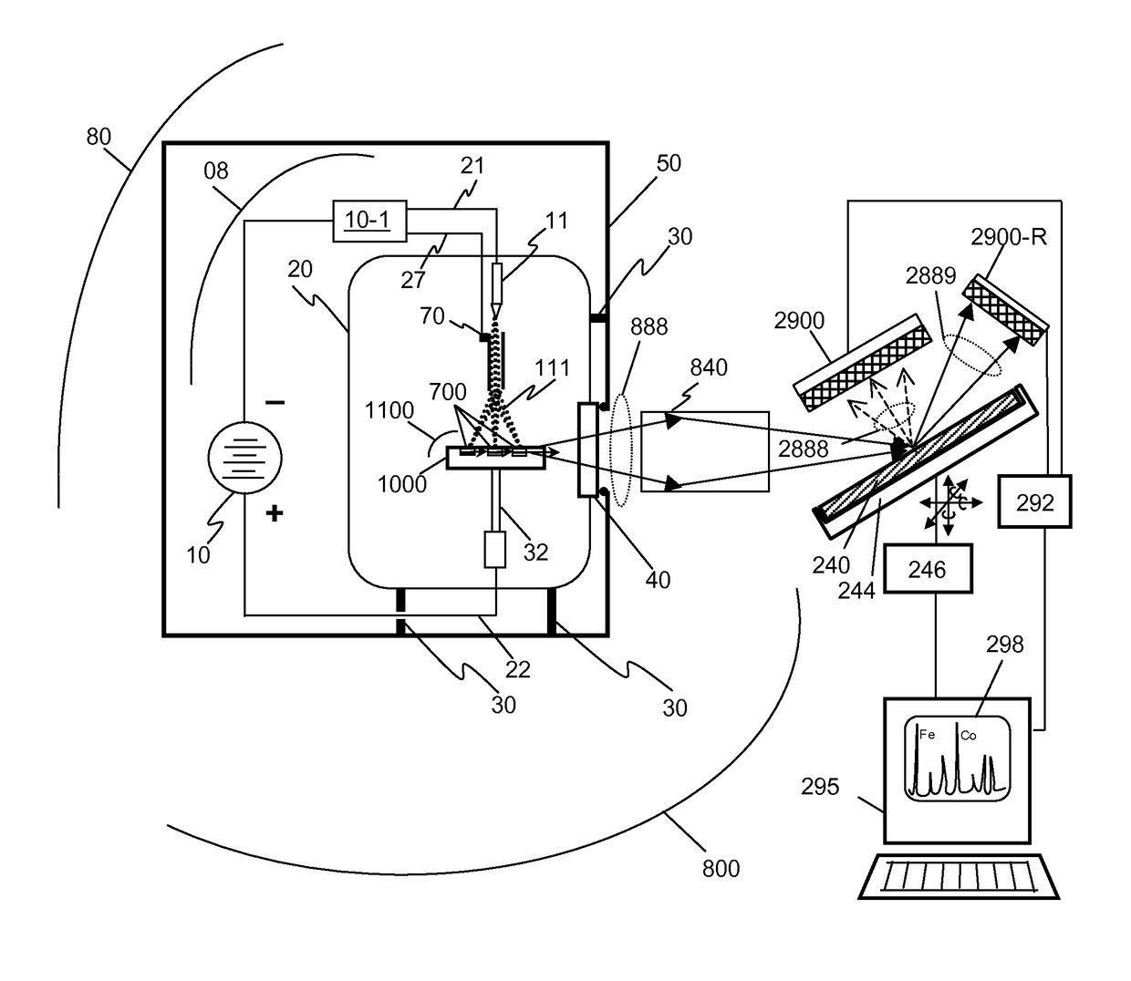
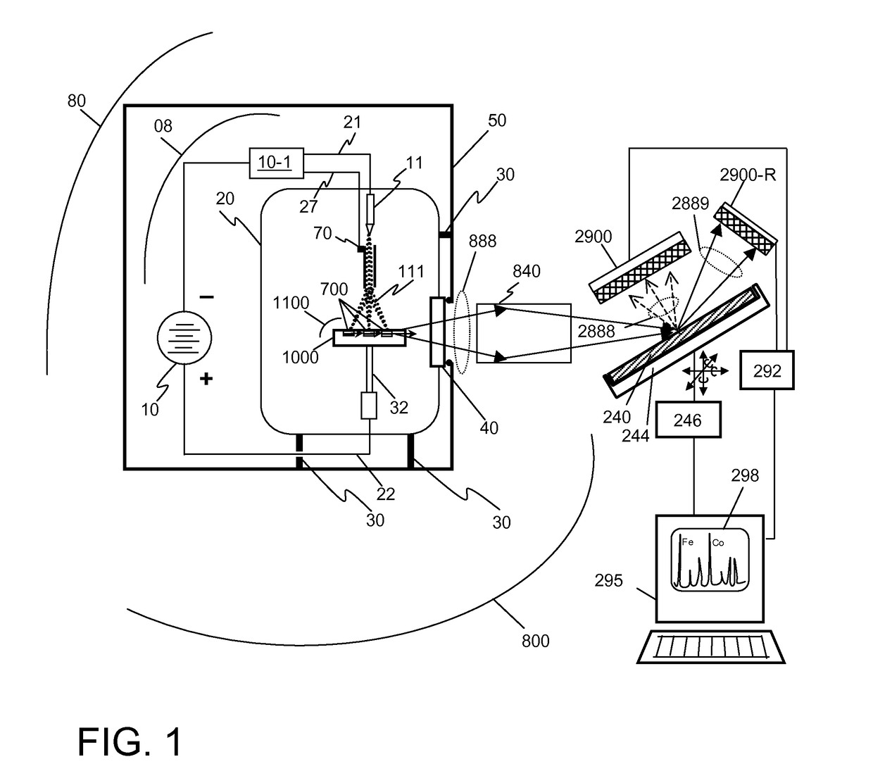
[0041]For all of the surface x-ray techniques mentioned above, the x-ray flux F of the x-ray beam incident on the sample surface is an important parameter and is equal to the product of the x-ray beam brightness Bs at the sample (defined as number of x-rays per unit area and per unit solid angle illuminating the sample), the cross sectional area A′ of the incident beam at the sample point, and the convergence angles: Δθ in the scattering plane which contains incident and reflected x-ray beam, and ω in the out-plane which is perpendicular to the reflection plane:

F=BsA′Δθ*ω  [Eqn. 1]

[0042]The x-ray beam brightness Bs at the sample is typically smaller than the x-ray source brightness (B) because the inherent low focusing efficiency and aberrations of the x-ray optical train lead to blurring and therefore an increase in the effective x-ray source size. Bs and B are approximately related by:

[0043]Bs=B⁢⁢ρ⁢s2s2+[M⁢⁢δ⁢ / ⁢(M+1)]2[Eqn.⁢2]

where ρ is the total focusing efficiency of the all the...


PUM

PropertyMeasurementUnit
thicknessaaaaaaaaaa
sizeaaaaaaaaaa
temperaturesaaaaaaaaaa

Abstract

This disclosure presents systems for total reflection x-ray fluorescence measurements that have x-ray flux and x-ray flux density several orders of magnitude greater than existing x-ray technologies. These may therefore useful for applications such as trace element detection and / or for total-reflection fluorescence analysis. The higher brightness is achieved in part by using designs for x-ray targets that comprise a number of microstructures of one or more selected x-ray generating materials fabricated in close thermal contact with a substrate having high thermal conductivity. This allows for bombardment of the targets with higher electron density or higher energy electrons, which leads to greater x-ray brightness and therefore greater x-ray flux. The high brightness / high flux source may then be coupled to an x-ray reflecting optical system, which can focus the high flux x-rays to a spots that can be as small as one micron, leading to high flux density.

Description

CROSS-REFERENCE TO RELATED APPLICATIONS[0001]This patent application claims the benefit of U.S. Provisional Patent Application Nos. 61 / 946,475 and 61 / 946,527, both filed on Feb. 28, 2014; 62 / 008,856, filed Jun. 6, 2014; 62 / 086,132, filed Dec. 1, 2014, and 62 / 117,062, filed Feb. 17, 2015, all of which are incorporated herein by reference in their entirety.FIELD OF THE INVENTION[0002]The present application presents an x-ray analysis and measurement apparatus for analysis, quantification of chemical composition, structural determination, measurements and metrology of a sample with a flat surface or for samples such as fine particles or liquid that are deposited on a flat surface of a substrate. The x-ray techniques may include total reflection x-ray fluorescence analysis (TXRF), grazing incidence x-ray diffraction (GIXRD), grazing incidence diffraction (GID), grazing incidence x-ray small angle scattering (GISAXS), and x-ray reflectivity (XRR), singularly or in combination.BACKGROUND ...

Claims


Application Information

Patent Timeline
Patent Type & Authority Patents(United States)
IPC IPC(8): H01J35/08G01N23/223G01N23/06H01J35/14G21K1/06G01N23/207G01B15/02
CPCG01N23/223G01B15/02G01N23/063G01N23/2076G21K1/06H01J35/08H01J35/14G21K2201/061G21K2201/064H01J2235/081H01J2235/086G01N23/085H01J35/12H01J35/147H01J35/153
Inventor YUN, WENBINGLEWIS, SYLVIA JIA YUNKIRZ, JANOS
Owner SIGRAY INC
Why Eureka
Try Eureka