Coaxial hollow cathode plasma assisted directed vapor deposition and related method thereof

a hollow cathode and plasma technology, applied in vacuum evaporation coatings, coatings, electric shock equipments, etc., can solve the problems of poor quality of high-speed growth, low utilization rate of evaporant materials in coatings, and restricted deposition, so as to achieve reliable coaxial plasma capability, increase particle energy, and reduce the effect of carrier gas consumption

Active Publication Date: 2017-05-02
FRAUNHOFER GESELLSCHAFT ZUR FOERDERUNG DER ANGEWANDTEN FORSCHUNG EV
View PDF54 Cites 0 Cited by
  • Summary
  • Abstract
  • Description
  • Claims
  • Application Information

AI Technical Summary

Benefits of technology

[0012]In addition to these features, an embodiment of the present invention provides, among other things, the approach that enables a robust and reliable coaxial plasma capability in which the plasma generating discharge is coaxial with the vapor plume, rather than the orthogonal configuration creating the previous disadvantages. In this way, the previous deformation of the vapor gas jet by the work gas stream of the hollow cathode pipe is avoided and the carrier gas consumption needed for shaping the vapor plume is significantly decreased. Second, instead of only one large hollow cathode pipe or slot, an annular arrangement of many small pipes can be used. Individual control of working gas flow and current for each pipe will enable the desired sweeping of the plasma plume in sync with the vapor jet. Third, some of the design variants described herein will contain means for magnetic tuning of the discharge. This is aimed at further increasing the particle energy as well as optimizing the spatial density distribution. Fourth, the components of the new plasma system can be designed with enhanced electric insulating capability up to the kV range. This will allow for biasing the plasma source with respect to the chamber (and / or substrate) and hence, performing heating or etching steps conveniently.

Problems solved by technology

Without applying additional aids, however, the layers grown at high rates are usually of poor quality.
Another drawback of conventional thermal evaporators—the fairly low utilization of the evaporant material when coating smaller substrates such as tools, engine parts or fibers—stems from the inherently divergent propagation characteristic of the vapor particles.
However, it was also found in the course of investigations that DVD at this stage was restricted to deposition of porous or columnar microstructures.
As in conventional EB-PVD, this is caused by the limited kinetic energy of the thermally generated vapor atoms.
For other applications or also for certain layers in the multilayer systems required in turbine blade coating, however, dense structures are demanded.
The conventional plasma assisted deposition process has several drawbacks, however.
Second, the conventional approach requires the use of high argon working gas flow rates which has adverse economic consequences.
Third, there is no means for sweeping the vapor plume from side to side (i.e. paint spraying a large area surface) in the conventional arrangement without significantly effecting the plasma properties.
Fourth, the conventional plasma generation approach provides inadequate cleaning, etching, and heating properties for some applications (i.e. the deposition of high temperature materials onto large area substrates).

Method used


Image

  • Coaxial hollow cathode plasma assisted directed vapor deposition and related method thereof
  • Coaxial hollow cathode plasma assisted directed vapor deposition and related method thereof
  • Coaxial hollow cathode plasma assisted directed vapor deposition and related method thereof

Examples


Embodiment Construction

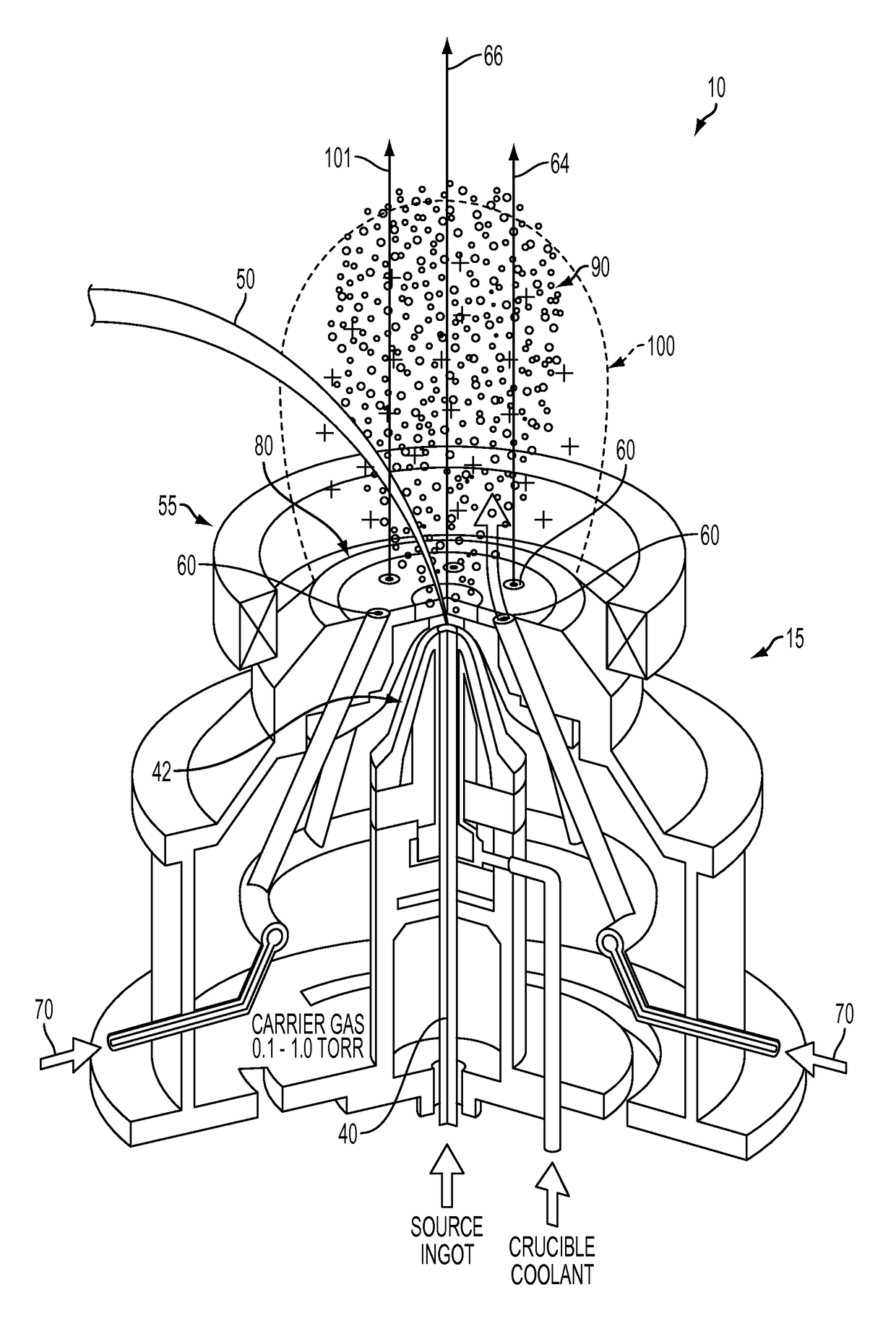
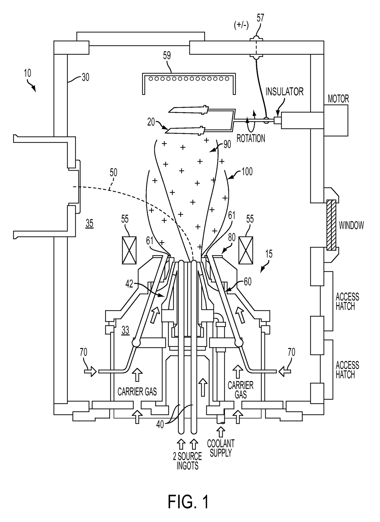
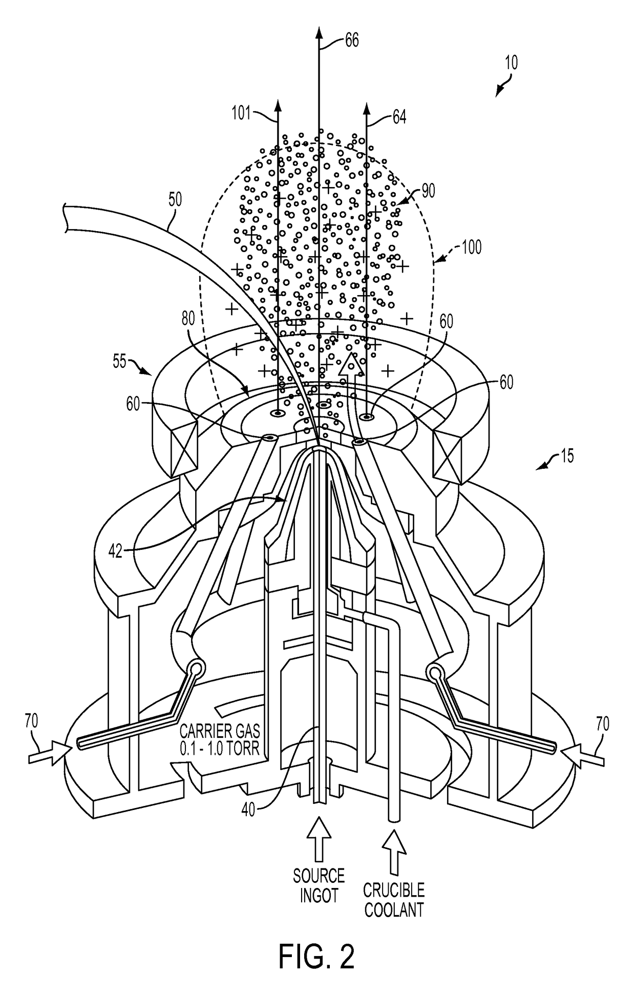
[0028]Turning now to the drawings, an aspect of an embodiment of the present invention, as shown in FIGS. 1-2, is a method and apparatus 10 for applying at least one coating onto at least one substrate 20 (e.g., sample), utilizing a plasma assisted directed vapor deposition process. The apparatus 10 may include a deposition chamber 30, having an upstream area 33, and downstream area 35, at least one evaporant source 40, at least one energetic beam 50 for impinging the evaporant source 40, at least one hollow cathode 60 aligned at least substantially coaxially with the evaporant source 40 for delivering a discharge current (not shown), at least one plasma-forming gas 70 (e.g., working gas) emitted from the hollow cathode 60, and at least one anode 80 for electrostatically attracting the discharge current from the hollow cathode 60. At least some of the elements included in the apparatus 10 may comprise a “nozzle”15, which may participate in applying at least one coating to at least o...


PUM

PropertyMeasurementUnit
bias voltageaaaaaaaaaa
discharge currentaaaaaaaaaa
momentumaaaaaaaaaa

Abstract

A plasma generation process that is more optimized for vapor deposition processes in general, and particularly for directed vapor deposition processing. The features of such an approach enables a robust and reliable coaxial plasma capability in which the plasma jet is coaxial with the vapor plume, rather than the orthogonal configuration creating the previous disadvantages. In this way, the previous deformation of the vapor gas jet by the work gas stream of the hollow cathode pipe can be avoided and the carrier gas consumption needed for shaping the vapor plume can be significantly decreased.

Description

RELATED APPLICATIONS[0001]This application is a national stage filing of International Application No. PCT / US2010 / 025259, filed Feb. 24, 2010, which claims priority under 35 U.S.C. §119(e) to U.S. Provisional Application Ser. No. 61 / 154,890, filed Feb. 24, 2009, entitled “Coaxial Hollow Cathode Plasma Assisted Directed Vapor Deposition and Related Method Thereof and U.S. Provisional Application Ser. No. 61 / 248,082, filed Oct. 2, 2009, entitled “Coaxial Hollow Cathode Plasma Assisted Directed Vapor Deposition and Related Method Thereof” the disclosures of which are hereby incorporated by reference herein in their entirety.BACKGROUND OF THE INVENTION[0002]Coatings applied by physical vapor deposition (PVD) processes—typically performed in a vacuum—are widely used in various applications such as in creating barrier layers for packaging films, metalizing plastics for flexible electronics and EMI shielding purposes, depositing scratch-proof, corrosion protection or decorative layers on v...

Claims


Application Information

Patent Timeline
Patent Type & Authority Patents(United States)
IPC IPC(8): C23C16/00H01J37/305C23C14/32C23C14/30C23C14/24C23C14/22H01J37/32H01J37/34
CPCH01J37/32596C23C14/228C23C14/246C23C14/30C23C14/32H01J37/3053H01J37/3233H01J37/32055H01J37/32357H01J37/32449H01J37/32568H01J37/34H01J37/32339H01J37/3244H01J2237/332
Inventor WADLEY, HAYDN N. G.MATTAUSCH, GOESTAMORGNER, HENRYROEGNER, FRANK-HOLM
Owner FRAUNHOFER GESELLSCHAFT ZUR FOERDERUNG DER ANGEWANDTEN FORSCHUNG EV
Why Eureka
Try Eureka