
Ionic air cooling device

a cooling device and air technology, applied in heat pumps, heating types, separation processes, etc., can solve the problems of needing to discharge spent brine into the environment, reducing the efficiency of the red system's membrane, and fouling of the membrane, so as to reduce the preferred temperature range, prevent corrosion, and reduce the effect of efficiencies over the prior ar

Active Publication Date: 2017-12-26
TANNER DAVID JOHN
View PDF1 Cites 6 Cited by
  • Summary
  • Abstract
  • Description
  • Claims
  • Application Information

AI Technical Summary

Benefits of technology

The patent aims to improve the efficiency of reversed-electro-dialysis processes by creating a highly efficient electrical output that has a very low carbon footprint. This is achieved by reducing the preferred temperature ranges between the ionic solutions, the use of at least one buffering tank, the use of two or more processing tanks, the use of intermediate ionic solution pathways, the selection of high valence temperature specific salts, the use of at least one automatic-flow-valve, the use of cathode-anode membranes, the utilization of electrode units coated with iridium oxides or titanium-niobium, the use of heat exchangers, and the use of industrial heat source input. The invention also involves utilizing sediment drains and activating processing tank sediments through the use of an automatic-flow-valve to further improve efficiency and recycle sediments.

Problems solved by technology

In the case of large supplies of available aqueous solutions, such as seawater and municipal fresh water supplies, reserved-electro-dialysis (“RED”) or pressure retarded osmosis factories constructed require a continual replenishment of ionic solutions used to conduct their salinity-gradient processes, causing the need to discharge of spent brine into the environment.
The solution sources in most RED systems utilize natural fresh water sources (such as rivers) and natural saltwater sources (such as the ocean, or a salt water lake) these sources of solution contain impurities that damage and reduce the efficiency of the RED system's membrane stacks or in the case of pressure retarded osmosis, these impurities cause fouling of the membranes.
This situation limits the overall efficiencies of such an open-ended, reversed-dialysis system.
Yet the wattage and power density of the ionic solution per unit volume generated by Loeb's system is low due to various factors including the temperature ranges preferred by Loeb.

Method used


Image

  • Ionic air cooling device
  • Ionic air cooling device
  • Ionic air cooling device

Examples


Embodiment Construction

[0007]An object of the present invention is to provide a method and apparatus using highly efficient means to generate air cooling.

[0008]Another object of the invention is to improve and extend the utility of the reversed-electro-dialysis processes, in addition to the pressure retarded osmosis process, according to the method and apparatus disclosed herein creating a highly efficient electrical output that has a very low carbon footprint—e.g. it is not reliant on consumption of fossil fuels, thus avoiding the production of greenhouse gas emissions. To the extent the invention disclosed herein causes net air cooling, its utility in the reduction of greenhouse gases could be especially useful.

[0009]A further object of this invention is to associate the disclosed method and apparatus with an industrial low grade heat source, such as the gasification of municipal solid waste, solar, or a gas stream input from for example a petroleum cracking facility, allowing the electrical voltage pot...


PUM


Abstract

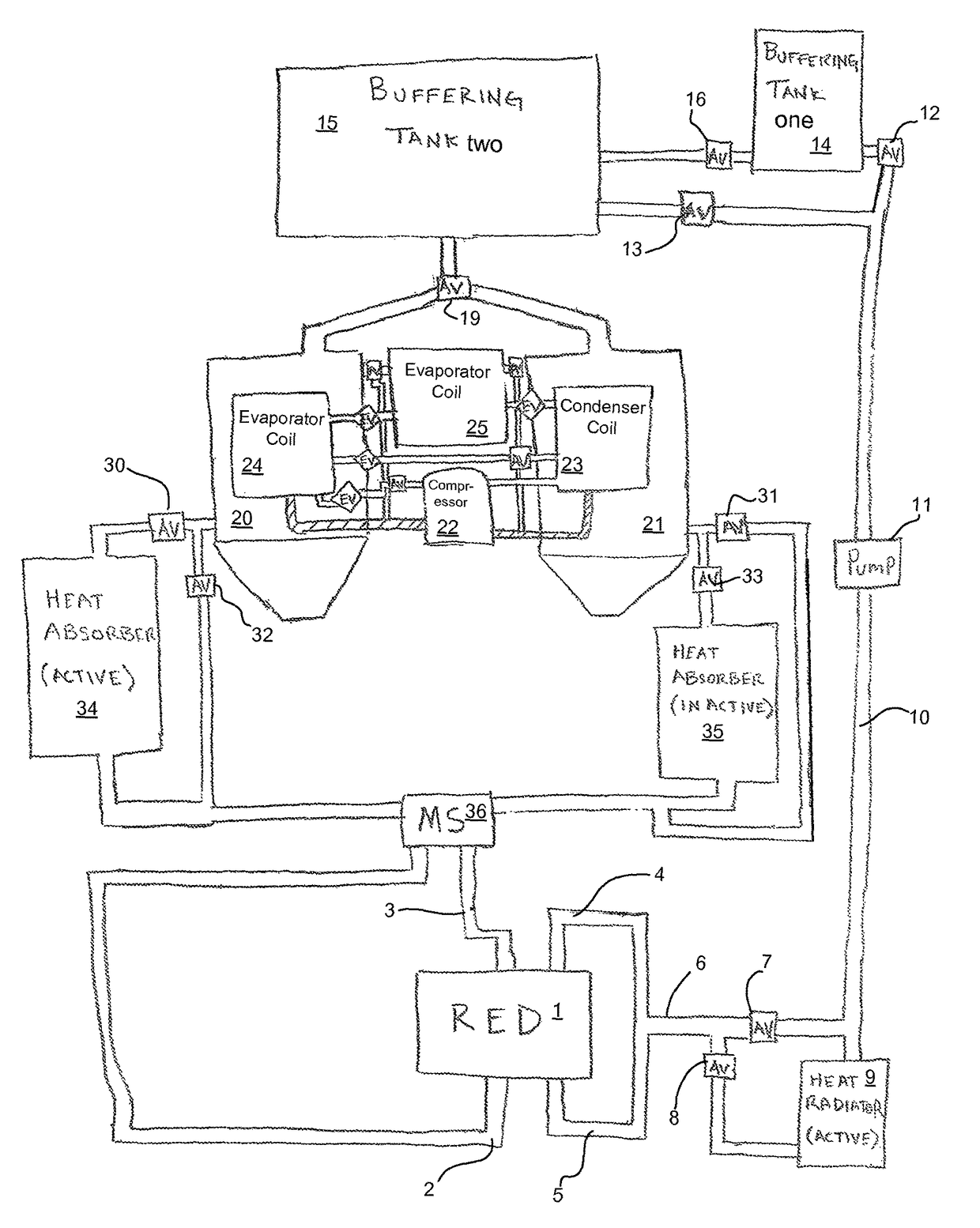
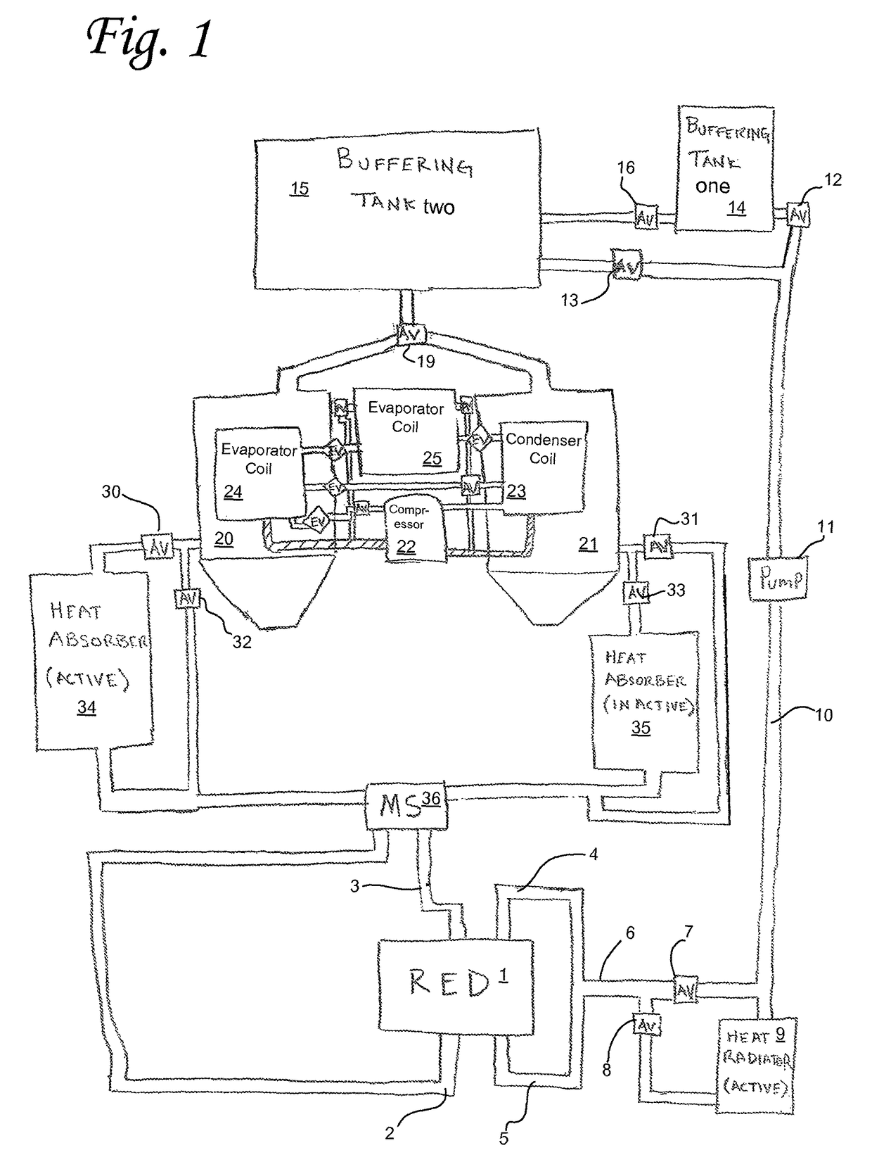
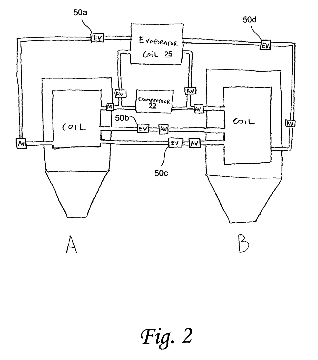
An ionic air cooling device comprising a salinity differential heat engine using a heat pump as the primary heat source and the mechanism by which the temperature differential is achieved. A closed loop thermodynamic cycle which produces a high thermodynamic efficiency in heat to energy conversion with a low temperature differential between the high and low sides, in addition to a net ambient temperature cooling effect by directly or indirectly converting ambient temperature / environmental low grade heat to electricity or potential kinetic energy or mechanical work. An ionic air cooling device which uses a salinity differential heat engine in which the heat energy can be converted to kinetic or electrical energy by means of pressure retarded osmosis, pressurized gas through volume confinement, or reversed electro dialysis.

Description

TECHNICAL FIELD[0001]The present invention, in some embodiments thereof, relates to air cooling systems and devices.BACKGROUND OF THE INVENTION[0002]It is well known in the prior art, electrical energy may be generated from the “free” energy produced by the mixing of two ionic solutions by a reversed-electro-dialysis or pressure retarded osmosis (PRO) processes. This process utilizes two ionic solutions of differing concentrations and temperature ranges, passing the solutions through a Reversed-Electro-Dialysis membrane stack, the dilute and concentrated solutions entering on either side of the membrane layer, causing solute to pass from the concentrated side to the dilute side, creating the generation of an electrical output across the electrodes located at either end of the membrane stack. The resulting electrical output is a function, generally speaking, of the difference in the concentrations of the inputted solutions, the type of salts utilized and the corresponding enthalpy of...

Claims


Application Information

Patent Timeline
Patent Type & Authority Patents(United States)
IPC IPC(8): F25B15/00F25B30/06B01D57/02
CPCF25B30/06B01D57/02F24F5/0007F25B13/00F25B2313/009F25B2313/021H01M8/227Y02E60/50
Inventor TANNER, DAVID JOHN
Owner TANNER DAVID JOHN
Learn More