
Electrical device

a technology of electric devices and negative electrodes, applied in the direction of electrochemical generators, cell components, batteries, etc., can solve the problems of inability to ensure the theoretical charge and discharge capacity of 372 mah/g, and the negative electrode material of carbon graphite, etc., and achieve the effect of excellent cycle durability

Inactive Publication Date: 2018-04-24
NISSAN MOTOR CO LTD
View PDF11 Cites 8 Cited by
  • Summary
  • Abstract
  • Description
  • Claims
  • Application Information

AI Technical Summary

Benefits of technology

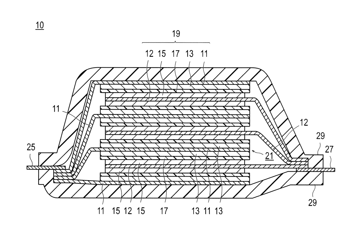
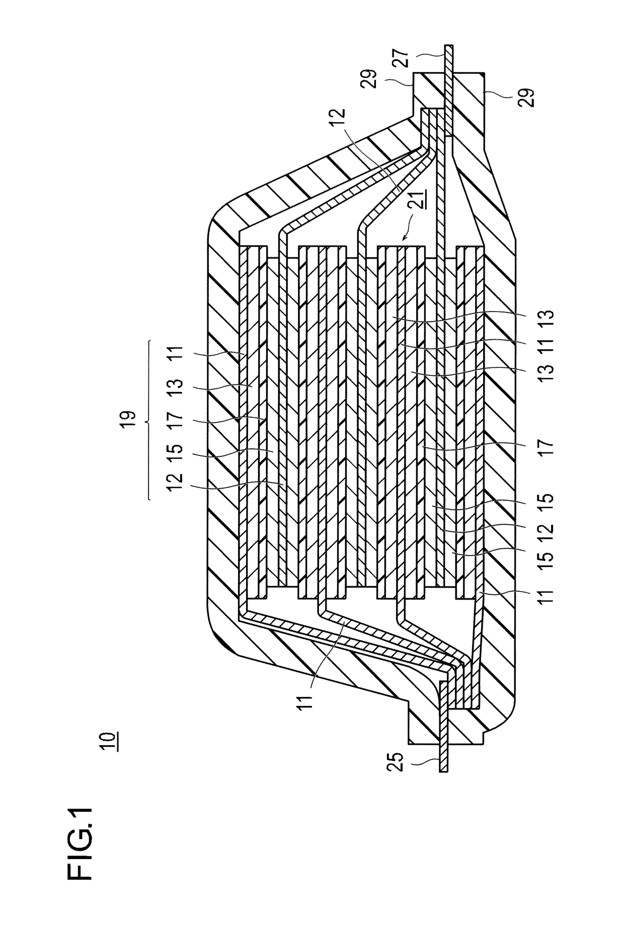
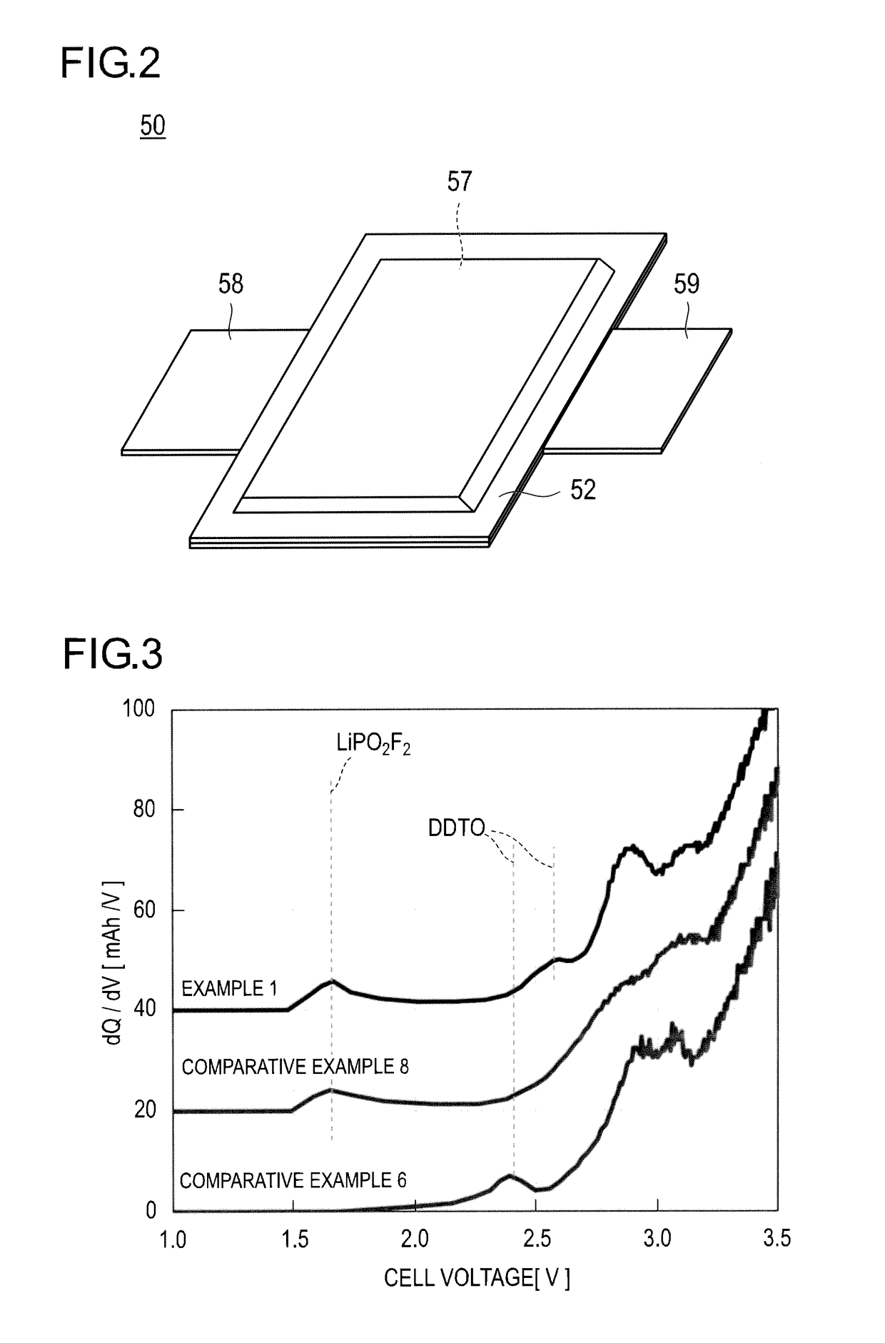
The invention involves a method for making a durable electrical device by forming a coating film on the electrodes using a specific chemical process. This coating film helps improve the device's performance and durability. The method involves using a specific chemical called LiPO2F2 to form a coating film on the positive and negative electrodes at a voltage of 2 V or less. Then, a second chemical called DDTO is used to form an excellent coating film on the negative electrode at a voltage of 2 to 3 V. This results in an electrical device with excellent cycle durability.

Problems solved by technology

However, the carbon graphite-based negative electrode material has the disadvantage that a theoretical charge and discharge capacity equal to or larger than 372 mAh / g, which is obtained from LiC6 as a compound introduced with maximum amount of lithium, cannot be ensured because the battery is charged and discharged by absorbing lithium ions into graphite crystals and desorbing the lithium ions therefrom.
Thus, by use of the carbon.graphite-based negative electrode material, it is difficult to ensure a capacity and energy density that are high enough to satisfy vehicle usage on the practical level.
However, as these intermediate oxides are thermodynamically unstable, it is very difficult for them to be present as a monocrystal.
However, since these LiySiOx have very small electron conductivity and SiO2 has no electron conductivity, there is a problem of having increased negative electrode resistance.
As a result, it becomes very difficult for lithium ions to get desorbed from a negative electrode active material or get absorbed into a negative electrode active material.
However, in a lithium ion secondary battery using the material alloyed with Li for the negative electrode, expansion-shrinkage in the negative electrode is large at the time of charging and discharging.
For example, volumetric expansion of the graphite material in the case of absorbing Li ions is approximately 1.2 times. However, the Si material has a problem of a decrease in cycle life of the electrode due to a large volumetric change (approximately 4 times) which is caused by transition from an amorphous state to a crystal state when Si is alloyed with Li.
In addition, when using the Si negative electrode active material, the battery capacity has a trade-off relationship with cycle durability.
Thus, there has been a problem that it is difficult to increase the capacity and improve the cycle durability concurrently.

Method used


Image

  • Electrical device
  • Electrical device
  • Electrical device

Examples


example 1

[0160](Preparation of Solid Solution Positive Electrode Active Material C1)

[0161]1. To 200 g of pure water, 28.61 g of manganese sulphate monohydrate (molecular weight 223.06 g / mol) and 17.74 g of nickel sulfate hexahydrate (molecular weight 262.85 g / mol) were added. The resulting mixture was stirred and dissolved to prepare a mixed solution.

[0162]2. Subsequently, ammonia water was dropwise added to the mixed solution until the pH became 7. A Na2CO3 solution was further dropwise added thereto, and a composite carbonate was precipitated (the PH was maintained to 7 with ammonia water while the Na2CO3 solution was dropwise added).

[0163]3. Thereafter, the precipitate was subjected to suction filtration, washed with water sufficiently, and then dried at 120° C. for five hours in a dry oven.

[0164]4. The dry powder was pulverized with a mortar, and then subjected to temporary calcination at 500° C. for five hours.

[0165]5. With the powder subjected to temporary calcination, 10.67 g of lithi...

example 2

[0195]A battery was manufactured in a similar manner to the above Example 1 except that a Si-containing alloy Si42Ti7Sn51 was used in place of SiOx as the Si material used for preparation of the slurry for a negative electrode. Here, the negative electrode manufactured in this Example is referred to as a negative electrode A2. The Si-containing alloy was manufactured by a mechanical alloying method. Specifically, zirconia pulverizing balls and raw material powders for an alloy were put into a zirconia pulverizing pot, and were alloyed at 600 rpm for 48 hours using a planetary ball mill apparatus P-6 manufactured by German Fritsch Co., Ltd.

[0196]The Si-containing alloy prepared above (Si42Ti7Sn51) has similar characteristics to another alloy which can be used in the present invention (an alloy other than Si42Ti7Sn51 among SixTiyGezAa, SixTiyZnzAa, and SixTiySnzA). Therefore, the alloy which can be used in the present invention brings about the same result as the present Example using...

example 3

[0197]A battery was manufactured in a similar manner to the above Example 2 except that Si34Sn21C45 was used in place of Si42Ti7Sn51 as the Si material (Si-containing alloy) used for preparation of the slurry for a negative electrode. Here, the negative electrode manufactured in this Example is referred to as a negative electrode A3.

[0198]The Si-containing alloy prepared above (Si34Sn21C45) has similar characteristics to another alloy which can be used in the present invention (an alloy other than Si34Sn21C45 among SixSnyAlzAa, SixSnyVzAa, and SixSnyCzA). Therefore, the alloy which can be used in the present invention brings about the same result as the present Example using Si34Sn21C45 or a similar result thereto.


PUM

PropertyMeasurementUnit
voltageaaaaaaaaaa
voltageaaaaaaaaaa
particle diameteraaaaaaaaaa

Abstract

To provide a means capable of further improving cycle durability in an electrical device such as a lithium ion secondary battery containing a positive electrode using a solid solution positive electrode active material. An electrical device has a power generating element containing a positive electrode in which a positive electrode active material layer containing a positive electrode active material is formed on a surface of a positive electrode current collector, a negative electrode in which a negative electrode active material layer containing a negative electrode active material is formed on a surface of a negative electrode current collector, and a separator impregnated with an electrolytic solution. The negative electrode active material layer contains a negative electrode active material represented by formula (1). The positive electrode active material layer contains a positive electrode active material (solid solution positive electrode active material) represented by formula (2). As the solid solution positive electrode active material contained in the positive electrode active material layer, a material having a composition represented by formula (3) as a basic structure is used. The electrolytic solution contains a predetermined additive.

Description

TECHNICAL FIELD[0001]The present invention relates to an electrical device. The electrical device according to the present invention is used for a driving power source or an auxiliary power source of a motor serving as, for example, a secondary battery or a capacitor for use in a vehicle such as an electric vehicle, a fuel cell vehicle, or a hybrid electric vehicle.BACKGROUND ART[0002]Recently, there has been a strong demand for reduction of the amount of carbon dioxide in order to deal with global warming. In the automobile industry, the reduction of emissions of carbon dioxide is highly expected in association with the spread of electric vehicles (EV) and hybrid electric vehicles (HEV). Thus, development of electrical devices such as secondary batteries for driving motors as a key to practical application of such vehicles is actively being carried out.[0003]The secondary batteries for driving motors are required to have quite high output performance and high energy as compared wit...

Claims


Application Information

Patent Timeline
Patent Type & Authority Patents(United States)
IPC IPC(8): H01M4/133H01M4/505H01M4/525H01M10/0567H01M4/134H01M10/0525H01M4/587H01M4/131H01M4/38H01M4/48H01M4/36
CPCH01M10/0567H01M4/131H01M4/134H01M4/364H01M4/386H01M4/483H01M4/525H01M4/587H01M10/0525H01M4/505Y02T10/7011H01M2220/20Y02E60/122Y02E60/10Y02T10/70
Inventor OGIHARA, WATARUYAMAMOTO, SHINJI
Owner NISSAN MOTOR CO LTD
Learn More