

Linear nano carbon tube composite-field emission source and method for preparing same and dedicated device therefor
A technology of carbon nanotubes and special devices, which is applied in nanostructure manufacturing, nanotechnology, nanotechnology, etc., and can solve the problems of equipment investment cost and power consumption increase
- Summary
- Abstract
- Description
- Claims
- Application Information
AI Technical Summary
Problems solved by technology
Method used
Image

Examples
Embodiment 1
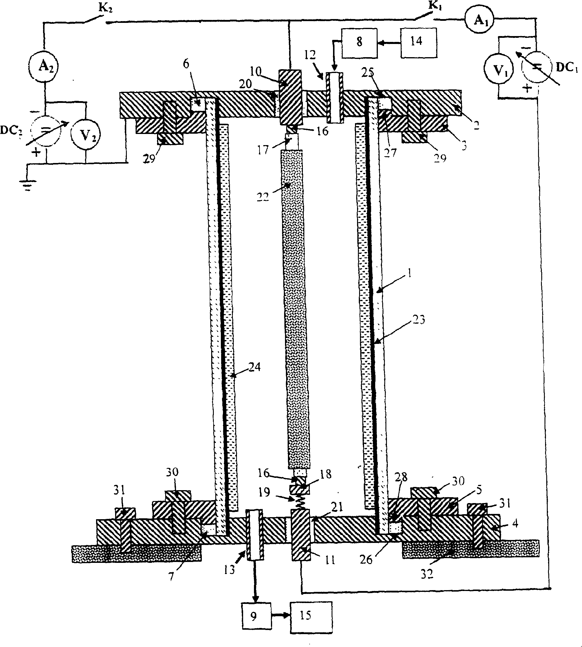
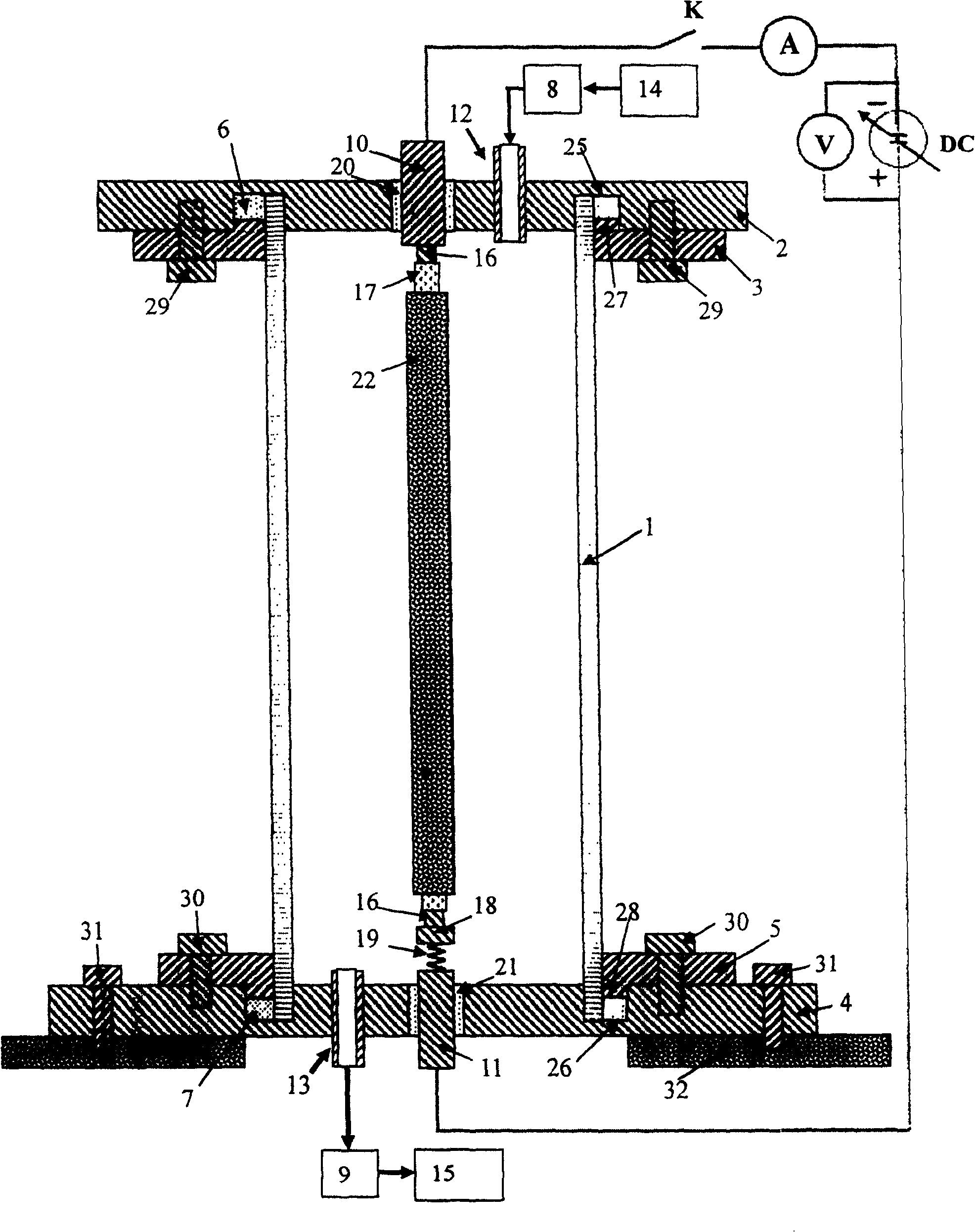
[0063] This example is for figure 1 The description of the special device for preparing the linear CNTs composite field emission source is shown. The device can be used to prepare the linear CNTs composite field emission source and to test the field emission and luminescence characteristics of the linear CNTs composite field emission source. In order to clearly show the structure of linear CNTs field emission source, in figure 1 The catalyst film 17 and the carbon nanotube film 18 on the fiber braided rope 16 are peeled off a small section downward or upward respectively. figure 1 The setup shown consists of a reaction chamber, a self-energizing loop, and a field emission test loop.
[0064] The reaction chamber is composed of a cylindrical cavity 1, first and second upper covers 2 and 3, first and second lower covers 4 and 5, and an air circuit system. Cylindrical cavity 1 is a domestic T-shaped fluorescent lamp glass tube with a length of 10 cm, a diameter of 3 cm, and a w...
Embodiment 2
[0075] In the device of this embodiment, the cylindrical cavity 1 adopts a domestic T-shaped fluorescent lamp glass tube with a diameter of 3 cm, a wall thickness of 1.2 mm, and a length of 30 cm. A transparent conductive ITO film with a thickness of 200nm was coated on the inner wall of the glass tube by sol-gel extraction method, and a layer of Nichia NP1045 white phosphor was deposited on the transparent conductive ITO film by electrophoresis with a thickness of 20 μm. Other parts of the device are the same as in Example 1.
[0076] The steps of making linear CNTs composite field emission source are as follows:
[0077] (1) Selection of fiber braided rope and its treatment: select a Fe-Al-Cr alloy fiber braided rope (fiber diameter of 1 μm) with a length of 30 cm and a diameter of 0.5 mm as the substrate material, and the Fe-Al- The Cr alloy fiber braided rope was placed in acetone and ethanol in sequence for ultrasonic cleaning, and then oxidized in air at 1000°C for 12 h...
Embodiment 3
[0085] In the device of this embodiment, the cylindrical cavity 1 adopts a domestic T-shaped fluorescent lamp glass tube, which has a diameter of 4 cm, a wall thickness of 1.4 mm, and a length of 50 cm. A transparent conductive ITO film with a thickness of 250nm was coated on the inner wall of the glass tube by sol-gel extraction method. A phosphor layer with a thickness of 30 μm was deposited on the transparent conductive ITO film by electrophoresis, and the phosphor was a German Osram-P22 green phosphor. Other parts of the device are the same as in Example 1.
[0086]The following introduces the steps of using this embodiment to make a linear CNTs composite field emission source:
[0087] (1) selection and processing of fiber braided rope: select long 50cm, Fe-Al-Cr alloy fiber braided rope (fiber diameter is 2 μ m) of diameter 1.0mm as substrate material, and by the method described in embodiment 2, to Fe-Al-Cr alloy fiber braided rope is cleaned and oxidized.
[0088] (...
PUM
| Property | Measurement | Unit |
|---|---|---|
| length | aaaaa | aaaaa |
| diameter | aaaaa | aaaaa |
| diameter | aaaaa | aaaaa |
Abstract
Description
Claims
Application Information