

Process for removing hydrogen sulphide from carbon bisulfide waste gas and apparatus therefor
A technology for hydrogen sulfide removal and exhaust gas desulfurization, which is applied in chemical instruments and methods, separation methods, dispersed particle separation, etc., can solve the problems of reduced catalyst activity, low operating costs, and complicated operations, and achieves reduced treatment costs and low operating costs , the effect of reducing operating costs
- Summary
- Abstract
- Description
- Claims
- Application Information
AI Technical Summary
Problems solved by technology
Method used
Image

Examples
Embodiment 1
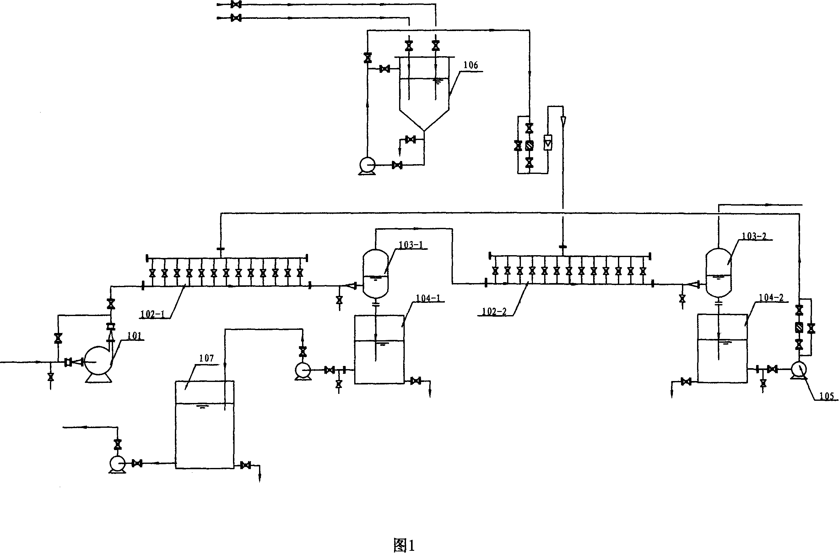
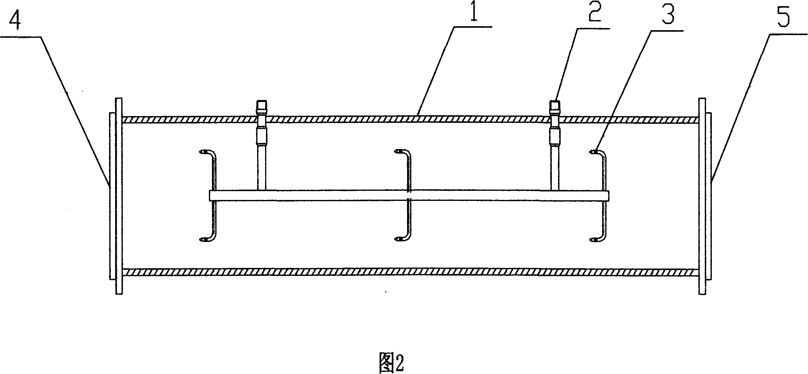
[0024] Example 1 The exhaust from the spinning machine to the cluster, the exhaust gas recovered by condensation in the plasticizing bath and the exhaust gas recovered by degassing in the acid bath are fed into the waste gas inlet 4 of the 1# pipe absorber 102-1 through the fan 101 at a speed of 25 m / s 1# tubular absorber 102-1 with a length of 10m and a diameter of 50mm, see attached drawing 2 for the structure, 6 sets of absorption liquid feed pipes 2 are installed in the pipe body 1, and each set of absorption liquid feed pipes 2 is equipped with a spray Head 3 (the spray head is a commercially available product), the absorption liquid feed pipe is connected to the absorption liquid circulation pump 105, the inlet of the circulation pump 105 is connected to the outlet of the mixed liquid tank 104-2, and the desulfurization gas outlet of the 1# tubular absorber 102-1 5. Connect to the inlet of double-block separator 103-1, and the waste gas outlet of double-block separator 10...
Embodiment 2
[0027] Example 2 The exhaust from the spinning machine to the cluster, the exhaust gas recovered by condensation in the plasticizing bath and the exhaust gas recovered by degassing in the acid bath are fed into the waste gas inlet 4 of the 1# tubular absorber 102-1 through the fan 101 at a speed of 100 m / s 1# tubular absorber 102-1 with a length of 20m and a diameter of 300mm, the structure is shown in attached drawing 2, 10 groups of absorption liquid feed pipes 2 are installed in the pipe body 1, and each group of absorption liquid feed pipes 2 is equipped with 6 spray nozzles Head 3 (the spray head is a commercially available product), the absorption liquid feed pipe 2 is connected to the absorption liquid circulation pump 105, the inlet of the circulation pump 105 is connected to the discharge port of the mixed liquid tank 104-2, and the 1# tubular absorber 102-1 desulfurizes the gas Outlet 5 is connected to the inlet of double-block separator 103-1, and the waste gas outle...
Embodiment 3
[0028] Example 3 The exhaust from the spinning machine to the cluster, the exhaust gas recovered by condensation in the plasticizing bath and the exhaust gas recovered by degassing in the acid bath are sent from the waste gas inlet 4 of the 2# tubular absorber 102-2 through the fan 101 at a speed of 50 m / s 2# tubular absorber 102-2 with a length of 40m and a diameter of 700mm (refer to Figure 1, omitting the 1# tubular absorber and supporting equipment), and 26 groups of absorption liquid feed pipes 2 are installed in the pipe body 1, each The group of absorption liquid feed pipes 2 is equipped with 10 spray heads 3, the absorption liquid feed pipe 2 is connected to the absorption liquid preparation tank 106, and sodium hydroxide is used in the absorption liquid preparation tank 106 to prepare the absorption liquid containing 200 g / L of sodium hydroxide It is sent to the tubular absorber 102-2 at 0.3 MPa, and the absorption liquid is atomized by the spray head 3, and the droplet ...
PUM
| Property | Measurement | Unit |
|---|---|---|
| clearance rate | aaaaa | aaaaa |
Abstract
Description
Claims
Application Information