Laser plastic micro-welding method

A welding method and plastic technology, applied in diffraction gratings, microlithography exposure equipment, photolithography exposure devices, etc., can solve the problem of unsatisfactory welding results, inability to weld micro-fine parts, and warping deformation of plastic parts And other issues

Inactive Publication Date: 2008-01-09
JIANGSU UNIV
View PDF1 Cites 4 Cited by
  • Summary
  • Abstract
  • Description
  • Claims
  • Application Information

AI Technical Summary

Problems solved by technology

One of its disadvantages is that it cannot weld micro-fine parts; the second disadvantage is that there is a relatively high rate of relative movement between the light source and the workpiece to be welded, which can easily cause

Method used


Image

  • Laser plastic micro-welding method
  • Laser plastic micro-welding method
  • Laser plastic micro-welding method

Examples


Embodiment Construction

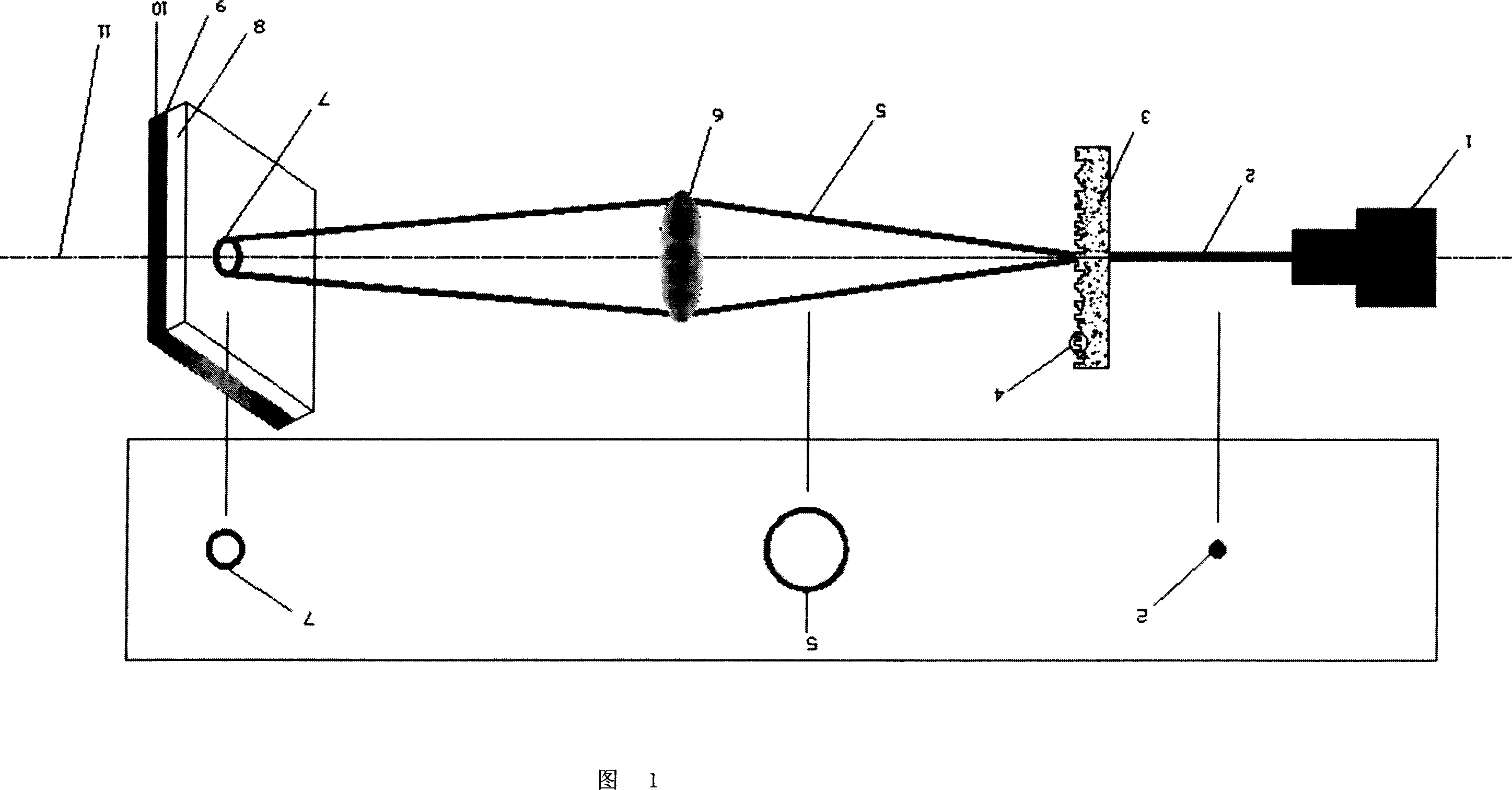
[0014] Now take the welding seam as an example to implement laser plastic micro-welding.

[0015] The welding plastics selected are: translucent polycarbonate (PC): length: 25mm, width: 25mm, thickness: 0.3mm; light-absorbing polycarbonate (PC): length: 25mm, width: 25mm, thickness: 3mm.

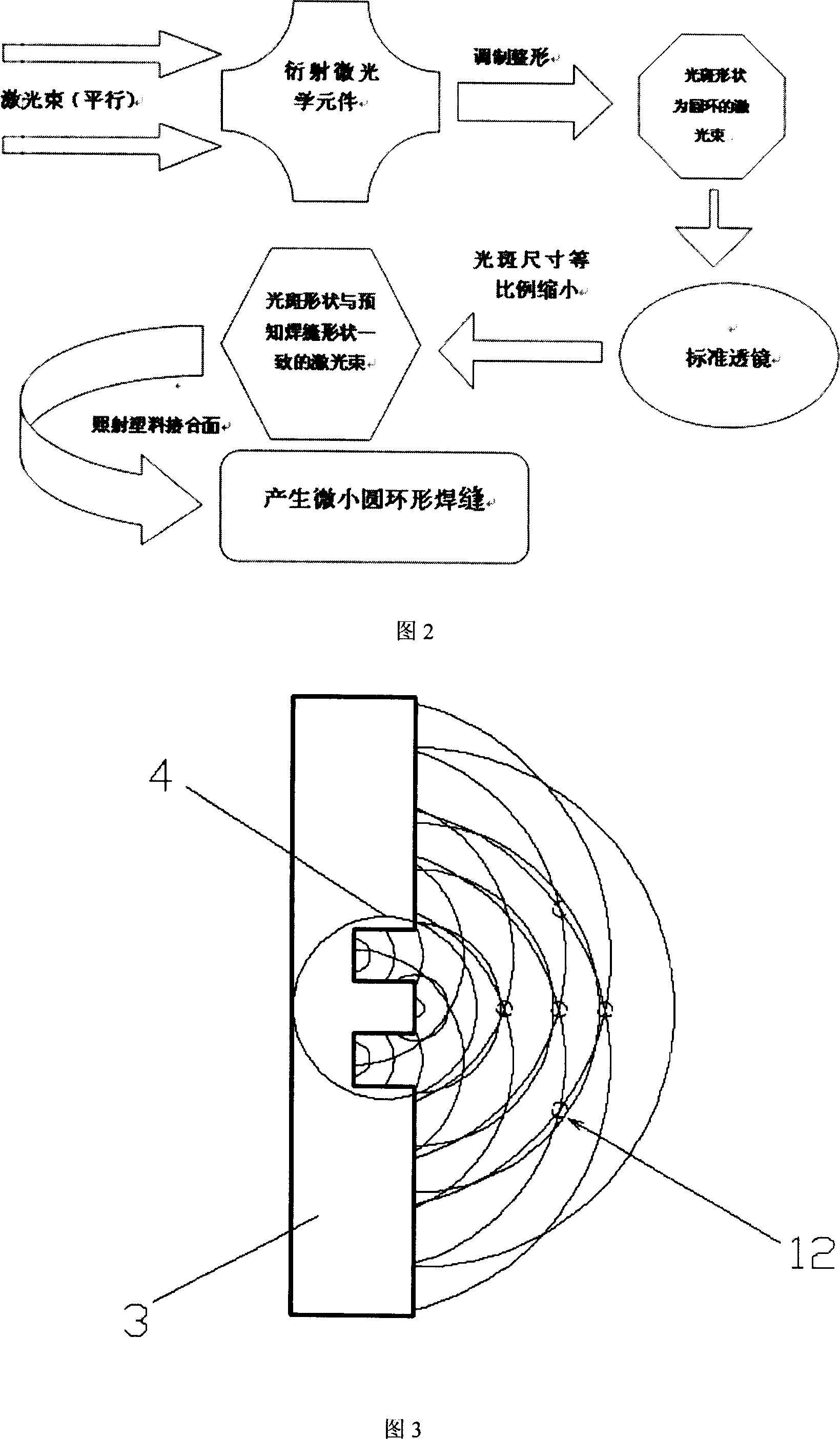
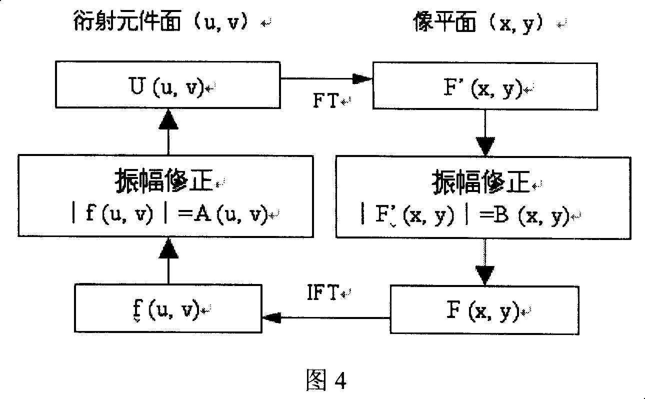
[0016] According to the two-slit diffraction mode, the diffraction equation can be obtained: y = mλD d , where y is Diffraction pattern size, m is the diffraction order, D is the distance between the slit and the screen, and λ is the wavelength of the laser beam. It can be seen from the equation that y is constant (the weld shape is known), m is a fixed value, and d is the distance between the two slits, that is, the characteristic size of the diffraction grating. Generally, the characteristic size of the diffraction grating is between 5 μm and 25 μm. According to the diffraction equation, it can be seen that the...


PUM

PropertyMeasurementUnit
Wavelengthaaaaaaaaaa

Abstract

The present invention relates to laser welding technology, and is especially laser micro welding process for plastic. Micro optical diffraction element is designed based on the weld seam shape and laser wavelength by means of proper algorithm, and formed on transparent chip material through reaction ion etching, UV photo etching or direct laser beam writing. Laser beam is made to pass through the micro optical diffraction element and one standard lens to form laser spot in the shape same as the weld seam for irradiating the joint of two plastic workpieces to complete the laser micro welding. The laser micro welding process for plastic has short processing time, no need of shifting laser beam and welded parts, small heat deformation and other advantages, and is suitable for batch production.

Description

technical field [0001] The invention relates to the field of laser welding, in particular to a laser plastic micro-welding method. The invention modulates and shapes the laser beam through optical elements, so that the shape of the laser beam spot is the same as that of the predicted welding seam, and finally performs synchronous welding on the plastic. This method has high welding efficiency and solves the problem of laser plastic microscopic Soldering problem. Background technique [0002] Traditional plastic welding techniques include: ultrasonic welding, vibration welding, hot plate welding, etc. The advantages of laser plastic welding are less resin degradation, less debris, and no pollution during the welding process due to the non-contact nature of the laser. Another major advantage is that laser plastic welding produces less vibration stress and thermal stress than other connection methods, which greatly improves the service life of products or internal components ...

Claims


Application Information

Patent Timeline
IPC IPC(8): B29C65/16G02B5/18G03F7/20
Inventor 王霄季进清张惠中刘会霞蔡兰
Owner JIANGSU UNIV
Why Eureka
Try Eureka