Permanent-magnet DC motor drive control system with approximate constant power pulling motor characteristics

A technology for motor drive control and traction motor, which is applied in the direction of speed/torque control of a single motor, electric components, and mechanical energy control, and can solve the problems of complex motor structure, reduced reliability, and poor control effect.

Inactive Publication Date: 2008-04-09
李平 +1
View PDF4 Cites 49 Cited by
  • Summary
  • Abstract
  • Description
  • Claims
  • Application Information

AI Technical Summary

Problems solved by technology

Such a multi-section protection circuit not only greatly increases the manufacturing cost of the battery pack, but also brings serious reliability problems: the more the number of sections, the more components of the protection circuit, and the worse the reliability
The prior art tries to solve this difficult problem from the following aspects, but unfortunately, most of the proposed solutions do not have ideal driving characteristics due to various shortcomings or deficiencies, so they have not been widely adopted or have not been practically applied:
[0014] In the prior art, one category is to try to improve the structure of the existing permanent magnet DC motor with constant magnetic field: for example, the hybrid excitation motor with auxiliary excitation winding is added. The disadvantage is that the motor structure is complicated, and the electric excitation also increases the power consumption. The efficiency is reduced and the manufacturing cost is significantly increased, and its constant power range is also very limited; some motors are designed as multi-phase motors, such as patent WO9941829: each winding coil is not connected to each other
The multi-phase scheme makes the motor structure and control circuit more complicated, and the number of high-power power electronic switching components increases significantly, which can only lead to a significant increase in system manufacturing costs, increased failure rates, and reduced reliability
[0015] Another type of improvement is to start with the drive control technology, such as the use of magnetization weakening technology: one of the methods is to use the armature reaction to weaken the magnetic flux. The disadvantage is: because the rare earth permanent magnet material has a strong coercive force, the constant power effect It is not obvious; another method - which is more widely used at present, for example, patent WO9601521 is to control the advance angle of current commutation - that is, to control the phase relationship of the current of the winding relative to the rotor flux vector, and its disadvantage is that it can be realized The constant power range is also very limited, and is limited by the maximum motor speed (usually no-load speed) and the maximum allowable current under constant power supply voltage
This kind of technology is also limited by the inductance of the motor winding, and its control effect is often not good.
[0016] Another solution is to use the method of controlling the product of the rotating speed and current to keep constant. Although this method can theoretically obtain the ideal constant power drive characteristics, it is difficult to control the permanent magnet brushless motor due to its strong control coupling. The establishment of linear mathematical models and state equations can only be achieved by using certain software technologies - such as fuzzy control
The disadvantage of this scheme is that it can only be realized by ensuring the stability of the control, realizing parameter self-tuning, and improving the robustness of the control process; in addition, this scheme is limited by the performance parameters of the battery and the motor.
[0017] Although some other design schemes in the prior art have also increased DC-DC converters at the front end of the permanent magnet DC motor speed control system as in the present invention, such as boosting and bucking of topology structures such as Boost, Buck, and Cuk Or buck-boost circuits, but they are only used to increase the voltage of the low-voltage rechargeable battery, improve the smooth speed regulation of the motor, reduce losses, and suppress or eliminate the torque ripple of the brushless DC motor, but no new control has been studied Method to solve the constant power problem of permanent magnet DC motor

Method used


Image

  • Permanent-magnet DC motor drive control system with approximate constant power pulling motor characteristics
  • Permanent-magnet DC motor drive control system with approximate constant power pulling motor characteristics
  • Permanent-magnet DC motor drive control system with approximate constant power pulling motor characteristics

Examples


Embodiment Construction

[0047] Since each partial component that constitutes the present invention has mature technologies, especially permanent magnet direct current brushed or brushless motors and their drive control technology, DC-DC converter technology, there is no fundamental difficulty in the implementation of the present invention.

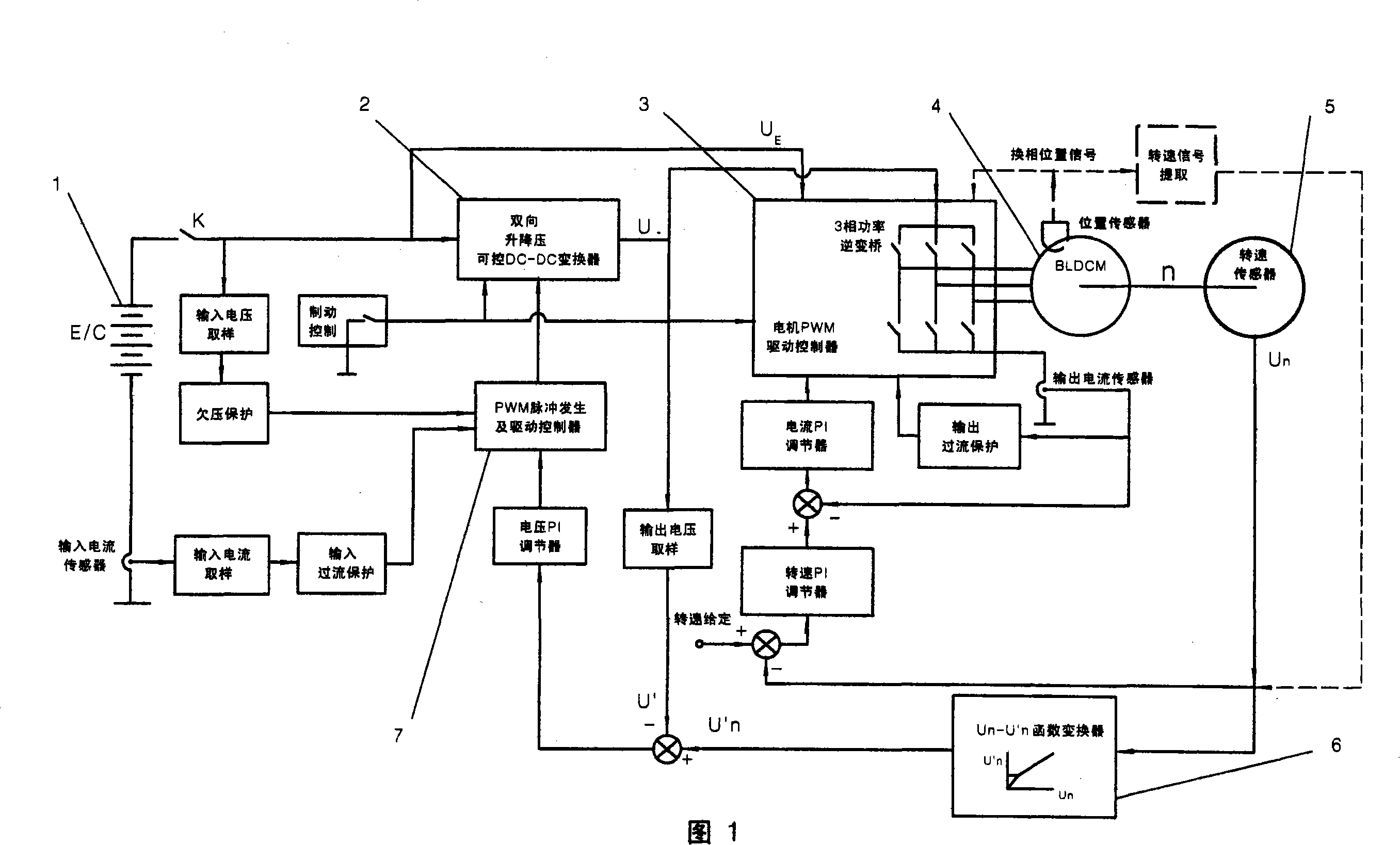
[0048] Figure 1 shows a DC permanent magnet brushless motor drive control system with approximately constant power traction motor characteristics.

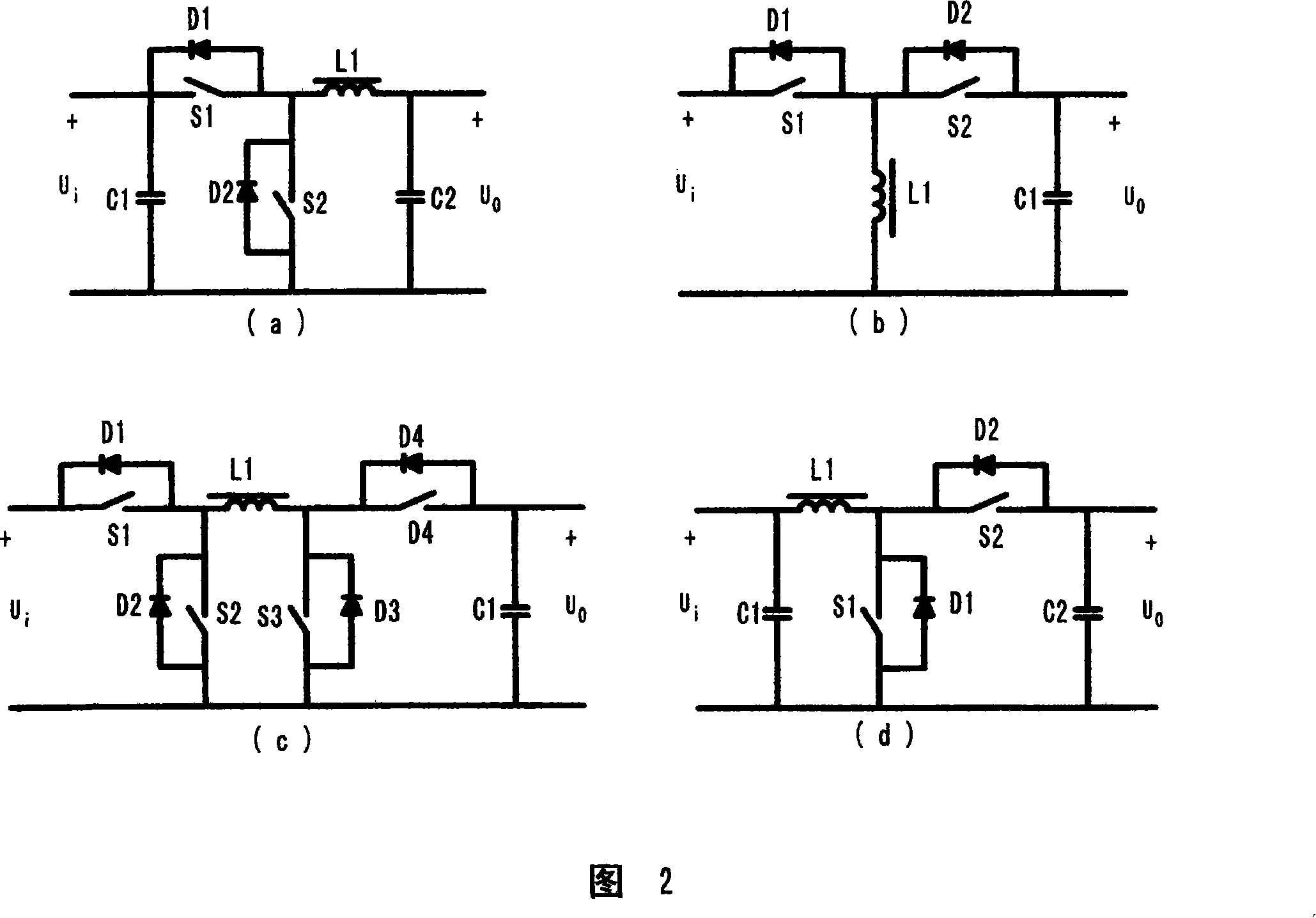
[0049] In Figure 1: 1 is a rechargeable battery or supercapacitor pack E / C, 2 is a bidirectional buck-boost controllable DC-DC converter, 3 is a motor PWM drive controller, and 4 is a permanent magnet brushless DC motor (BLDCM) , 5 is the speed sensor, 6 is the Un-U'n function converter that converts the output signal Un of the speed sensor into the control signal U'n of the output voltage of the bidirectional buck-boost controllable DC-DC converter, and 7 is the PWM pulse generation and drive controller.

[0050] T...


PUM


Abstract

A permanent-magnetic DC motor bearing similar characteristics with the constant power pulling motor, in particular a new drive control system for brushless motor adopts new technologies of full electronic drive control and DC-DC transducer. The motor can generate great drive torque, i.e. high tractive force, climbing ability and better acceleration performance with low power consumption, and eliminate the needs for improvement to the motor structure, complication, high manufacture cost or weak magnetic control; the motor may further gain such performance as high speed, wide speed regulation and infinite variable speed under light load; the total voltage of the battery and the number of single series of connection can be reduced; controllable electric brake can be realized through fully utilizing the energy feedback during sliding and braking. The new system can significantly improve the kinetic performance, safety and reliability of electric vehicles and remarkably reduce operating costs, with ideal characteristics expected in various electric vehicles powered by rechargeable battery or/and super capacitance as well as significantly expanded work scope and capacity for conventional electrically driven system.

Description

technical field [0001] The invention relates to a permanent magnet DC motor drive control system with wide speed regulation, large drive torque and low power consumption, which has the characteristics of an approximate constant power traction motor. The motors used in this system do not require field weakening, but can operate at speeds higher than the base speed at rated voltage. The drive characteristic of this system is similar to its excitation motor and traction motor, which is equivalent to the electronic modern simulation version of the traditional motor-mechanical speed change system, and belongs to the field of motor drive control. The permanent magnet direct current motor applicable to the present invention also includes a mechanical and electrical integrated assembly that directly connects the permanent magnet direct current motor and the mechanical reducer and tightly combines them together without mechanically changing the speed. The reducer is a fixed reduction r...

Claims


Application Information

Patent Timeline
Patent Type & Authority Applications(China)
IPC IPC(8): H02P6/06H02P6/08H02K7/116
Inventor 李平
Owner 李平
Why Eureka
Try Eureka