Dorsal mode light acoustic imaging method based on multiple phase control focusing ring array

A photoacoustic imaging and focusing ring technology, which is applied in the generation of ultrasonic/sonic/infrasonic waves, can solve the problems of poor directivity and signal-to-noise ratio, inability to achieve dynamic focus, and narrow direction directivity, etc., to achieve narrow aperture angle, Effects of improving operability and application range and improving imaging resolution

Inactive Publication Date: 2011-07-27
JIANGXI SCI & TECH NORMAL UNIV
View PDF0 Cites 0 Cited by
  • Summary
  • Abstract
  • Description
  • Claims
  • Application Information

AI Technical Summary

Problems solved by technology

A large-aperture high-frequency focusing detector can obtain a good signal-to-noise ratio, but its focal spot and focal length limit its imaging resolution and imaging angle, and the rapid attenuation of the signal in the tissue also limits its detection depth; The electric disc detector has a very high time resolution, and the longitudinal resolution of the three-dimensional imaging can reach tens of microns, but its directivity and signal-to-noise ratio are poor; the double-ring detector has a narrow aperture angle and a certain directionality , but its small aperture makes the signal-to-noise ratio of the acquisition poor, and it cannot achieve dynamic focusing in the depth direction

Method used


Image

  • Dorsal mode light acoustic imaging method based on multiple phase control focusing ring array
  • Dorsal mode light acoustic imaging method based on multiple phase control focusing ring array
  • Dorsal mode light acoustic imaging method based on multiple phase control focusing ring array

Examples


Embodiment 1

[0024] Embodiment 1 Device of the present invention

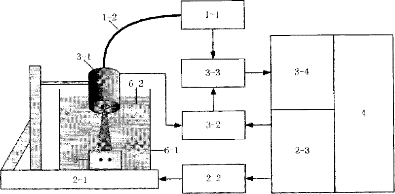
[0025] figure 1 It is a device structure diagram of the present embodiment, and the names of the components shown in the figure are: laser generator 1-1, optical fiber 1-2, three-dimensional scanning platform 2-1, stepping driver 2-2, digital I / O control Card 2-3, multi-element ring array detector 3-1, signal preprocessor 3-2, digital oscilloscope 3-3, GPIB bus communication card 3-4, computer 4, sample stage 5, sample cell 6-1, acoustic Coupling solution 6-2. The device of the invention is composed of a laser generating component, a step scanning component, a photoacoustic signal collecting component, an acoustic coupling component, a sample fixing component, a computer and the like. Among them, the laser generating component is composed of a laser 1-1 connected with an optical fiber 1-2; the step scanning component is controlled by a computer 4 through a digital I / O control card 2-3 and a step driver 2-2 to control the ...

Embodiment 2

[0030] Embodiment 2 preferred method of the present invention

[0031] (1) Fix the object to be tested on the sample stage, use a pulsed laser with a wavelength of 400nm to 2500nm to incident on the sample to be tested, and stimulate the sample to be tested to generate a photoacoustic signal;

[0032] (2) Under the control of the LabVIEW acquisition program, the three-dimensional scanning platform drives the multi-element ring array detector and the sample to be tested to collect the photoacoustic signal step by step, and collect the photoacoustic signal data at the same time;

[0033] (3) Using MATLAB software to preprocess the collected signal and calculate the image reconstruction of the phase control focusing through the computer, and then obtain the image of the object to be measured through the back projection algorithm.

Embodiment 3

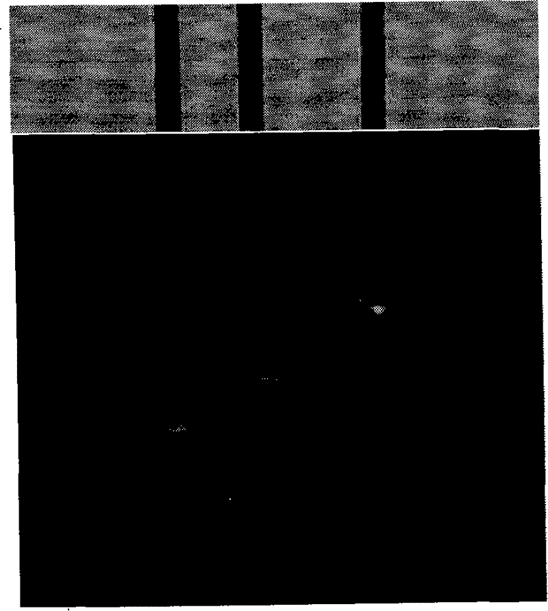
[0035] The apparatus of Example 1 and the method of Example 2 were used to image the agar embedded with carbon rods.

[0036] Three carbon rods were buried linearly and vertically in the agar, the burial depths were 4.5mm, 6mm and 7.2mm, and the distances between them were 1.8mm and 2.5mm respectively, and the diameter of the carbon rods was 0.5mm. The three-dimensional scanning platform drives the multi-element ring array acoustic detector to step-scan to collect photoacoustic signals, and the scanning step is 0.1 mm. The rotation angle of the sample is 180°, and the rotation step of the stepper motor is 18°. The resulting image is as image 3 shown. Depend on image 3 It can be seen that the test sample can be clearly and accurately imaged by using the present invention.


PUM

PropertyMeasurementUnit
wavelengthaaaaaaaaaa

Abstract

The invention provides a multiple phase control focus ring array-based dorsad mode optical acoustic imaging method; steps of the method are as follows: (1) the pulsed laser is used to irradiate a sample to be tested; (2) the sample to be tested or a multi-ring array detector receives optical acoustic signals by the dorsad mode of a step motor driving scan, and simultaneously acquires the data of optical acoustic signals; (3) data processing software is used to calculate the phase control of the acquired optical acoustic signals for realizing the dynamic focus mode A scan in the depth Z direction, and by the two-dimensional data scanning in the X-Y direction of the step motor point-to-point, a three-dimensional optical absorption distribution map can be synthesized by the back projection. The method has the advantages that due to the adoption of the multi-ring array detector, the super narrow aperture angle and the good direction pointing of the multi-ring array detector greatly improve the imaging resolution, and realize the focus scan imaging in both X and Y directions; due to the adoption of the calculation phase control focus technology, the signal to noise ratio of signals canbe effectively improved, and the mode A dynamic focus scan imaging in the depth Z direction can be realized; due to the receiving of optical acoustic signals in the dorsad mode, the operability and the application range of the system are greatly improved.

Description

technical field [0001] The invention relates to a test measurement and imaging method, in particular to a back-mode photoacoustic imaging method based on a multi-element phased focus ring array. Background technique [0002] At present, there are three measurement modes of photoacoustic imaging: forward, side and back mode: [0003] Due to the high scattering properties of biological tissues, the applicable range of forward mode systems is very small. [0004] Lateral mode systems usually obtain the distribution of photoacoustic pressure in a certain plane by means of detector rotation scanning, sample rotation scanning, and plane linear scanning, and then deduce the spatial light absorption distribution image through a specific reconstruction algorithm. This method has a high spatial resolution, but its time resolution is low, the imaging algorithm is complex, and the spatial directionality is poor. Moreover, due to the limitation of the characteristics of the organism, th...

Claims


Application Information

Patent Timeline
Patent Type & Authority Patents(China)
IPC IPC(8): G01N29/34
Inventor 曾吕明刘国栋任重黄振
Owner JIANGXI SCI & TECH NORMAL UNIV
Why Eureka
Try Eureka