Laser beam optical fiber transmission device in laser sodium guiding technology

A laser sodium guide star and optical fiber transmission technology, applied in the direction of optical waveguide light guide, optical waveguide coupling, cladding optical fiber, etc., can solve the problems of not meeting the technical performance requirements of sodium guide star, high cost, complex transmission system, etc., to achieve The effect of low cost, low difficulty and high transmission capacity

Inactive Publication Date: 2008-09-24
INST OF OPTICS & ELECTRONICS - CHINESE ACAD OF SCI
View PDF0 Cites 11 Cited by
  • Summary
  • Abstract
  • Description
  • Claims
  • Application Information

AI Technical Summary

Problems solved by technology

Whether a single ordinary single-mode fiber or a photonic crystal single-mode fiber is used, it cannot meet the performance requirements of the sodium guide star technology in the adaptive optics system of a large-aperture astronomical telescope in terms of power.
The third stage: In order to overcome this difficulty, the European Southern Observatory uses a single-mode photonic crystal fiber with a large core diameter and an external electro-optical phase modulation system to realize the beam transmission (W.Hackenberg, M.Zaehringer and A.Silber.SPIE, 627262724D) , the transmission scheme introduces an external electro-optic phase modulation system with a complex structure, and the entire transmission system is relatively complicated; in addition, the cost of the external electro-optic phase modulator and large-core single-mode photonic crystal fiber involved in the transmission system is relatively high

Method used


Image

  • Laser beam optical fiber transmission device in laser sodium guiding technology
  • Laser beam optical fiber transmission device in laser sodium guiding technology
  • Laser beam optical fiber transmission device in laser sodium guiding technology

Examples


Embodiment Construction

[0025] The present invention will be described in detail below in conjunction with the accompanying drawings and specific embodiments.

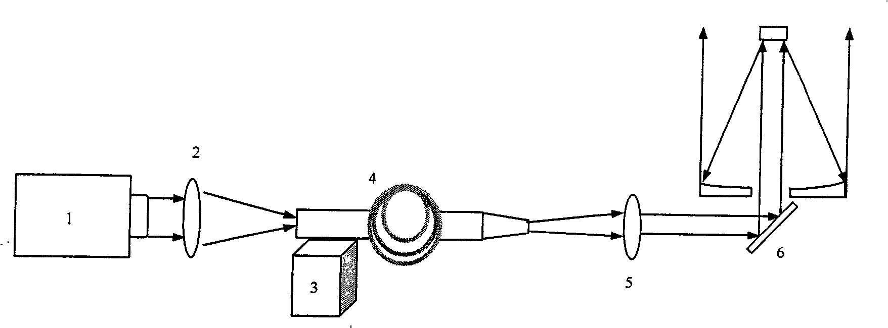
[0026] figure 1 For adopting the optical fiber transmission device of the present invention to realize the application schematic diagram of the laser beam from the laser to the transmitting telescope in the laser sodium guide star technology; as figure 1 As shown, the laser beam is emitted from the laser 1 and enters the coupling lens 2. After being adjusted by the coupling adjustment device 3, it is incident on the input end face of the transmission device 4 according to the requirements, and then exits from the output end face of the transmission device 4, and reaches the emission through the collimator lens 5. Telescope6.

[0027] The optical fiber transmission device 4 in this embodiment will be described in detail below.

[0028] 1. The structure of optical fiber transmission device

[0029] In the laser sodium guide star technology, ...


PUM

PropertyMeasurementUnit
radiusaaaaaaaaaa
diameteraaaaaaaaaa
lengthaaaaaaaaaa

Abstract

A laser beam optical fiber transmission device of a laser sodium guide star technology is characterized in that: the device uses a cylindrical multimode optical fiber for producing a conical shape by adopting the melt-pulling method for pulling, then a table is formed by grinding, the device comprises: a cylindrical multimode optical fiber part and a conical table optical fiber part, the conical table optical fiber part is formed at the tail end of the cylindrical multimode optical fiber by direct processing, the other end of the cylindrical multimode optical fiber is an input end of a laser beam, the other end of the conical table optical fiber is an output end of the laser beam, the length of the cylindrical multimode optical fiber is equal to 1 to 1.2 times of the distance from a laser to a transmitting telescope; the radius of a fiber core of the conical table optical fiber which is arranged at the thick end is equal to the radius of the fiber core of the cylindrical multimode optical fiber, and the radius of the fiber core of the conical table optical fiber which is arranged at the thin end meets the single-mode condition for transmitting the laser by the optical fiber. The optical fiber transmission device has the advantages of simple and flexible structure and low cost, the quality of the output light beam is close to the diffraction limit, at the same time, the optical fiber transmission device can effectively overcome the non-linear scattering and other effects during the optical fiber transmission, thus achieving the purpose of transmitting the higher laser power.

Description

Technical field: [0001] The invention belongs to the beam transmission field in the laser sodium guide star technology of an adaptive optics astronomical telescope system, in particular to a transmission device for a laser beam from a laser to a transmitting telescope. Background technique: [0002] Laser guide star technology provides a solution to the beacon problem for the application of adaptive optics system in star observation and space observation. Its principle is to launch a high-power, high-beam-quality laser beam into the sky, and use the backward Rayleigh scattering produced by the laser in the stratosphere or the sodium resonance fluorescence scattering produced in the exosphere as a beacon. An integral part of this technology is directing the laser light from the laser to the telescope launch system. The distance from the laser to the telescope launch system depends on the layout of the telescope system. Generally speaking, the larger the aperture of the prima...

Claims


Application Information

Patent Timeline
Patent Type & Authority Applications(China)
IPC IPC(8): G02B6/25G02B6/32G02B6/02G02B1/10C03B37/012
Inventor 李斌成肖志刚
Owner INST OF OPTICS & ELECTRONICS - CHINESE ACAD OF SCI
Why Eureka
Try Eureka