Method for nano ZnO film preparation by screen painting and luminous tubes using the film

A technology of screen printing and light-emitting tubes, applied in the field of field emission display, to achieve the effects of increased stability and service life, low production cost, and easy large-scale production

Inactive Publication Date: 2008-12-31
BEIFANG UNIV OF NATITIES
View PDF0 Cites 3 Cited by
  • Summary
  • Abstract
  • Description
  • Claims
  • Application Information

AI Technical Summary

Problems solved by technology

At present, there are many methods for preparing ZnO thin films, such as magnetron sputtering, metal organic chemical vapor deposition-MOCVD, molecular beam epitaxy-MBE, pulsed laser deposition (PLD) and laser molecular beam epitaxy (L-MBE), but these growth None of these methods can obtain ZnO thin films uniformly over a large area.

Method used


Image

  • Method for nano ZnO film preparation by screen painting and luminous tubes using the film
  • Method for nano ZnO film preparation by screen painting and luminous tubes using the film

Examples


preparation example Construction

[0042] The preparation method of the above-mentioned luminous tube is as follows:

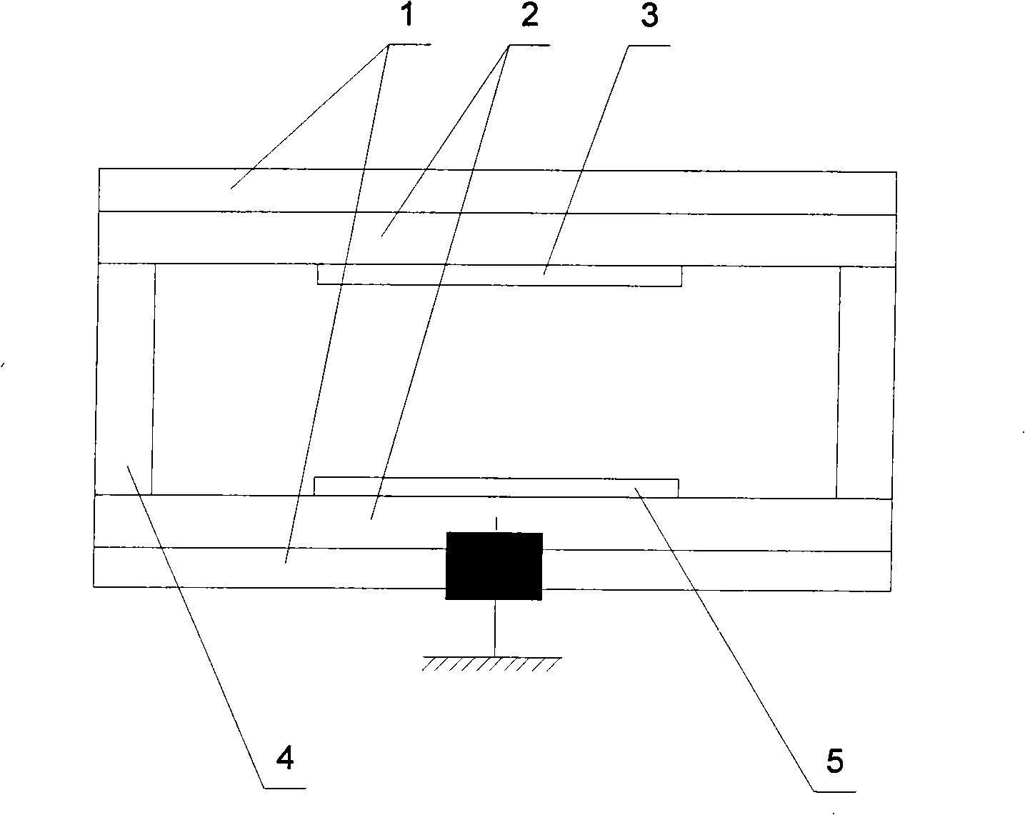
[0043] (1) cathode preparation, with the inventive method on the ITO layer of ITO conductive glass 1, print ZnO thin film 5;

[0044] (2) Anode preparation, on the ITO layer of another ITO conductive glass 1, according to the photolithography of lead wire and assembly requirements, phosphor powder is coated on it to form phosphor film 3;

[0045] (3) Fix two pieces of ITO conductive glass 1 with insulating column 4 and keep it parallel to each other;

[0046] (4) Finally, the anode and the cathode are respectively drawn out from the two ITO layers by firing the silver paste, and then the two pieces of ITO conductive glass 1 are sealed and vacuumized before being packaged.

[0047] The working principle of the ZnO thin film field emission luminous tube of the present invention is:

[0048]Ground the cathode of the field emission light-emitting tube, and apply a positive voltage to the anode. W...

Embodiment 1

[0050] A kind of screen printing prepares the method for nanometer ZnO film, comprises the following steps:

[0051] a. Preparation of ZnO slurry

[0052] Add nanometer ZnO in terpineol by weight ratio 3: 10, ultrasonic dispersion 8 hours or to nanometer ZnO fully disperse in terpineol, after crossing 130 mesh sieves, press pulping agent and aforementioned mixture (nano ZnO and terpineol alcohol) in a weight ratio of 3:10, add methyl cellulose, then heat and stir at 400K, then pass through a 420 mesh sieve again, and cool naturally to room temperature for use;

[0053] b. Preparation of ZnO thin films by screen printing

[0054] Select the mesh number as 350 mesh wire mesh or polyester mesh, and use the ZnO slurry obtained in the previous step to screen print on the ITO conductive glass by a screen printing machine;

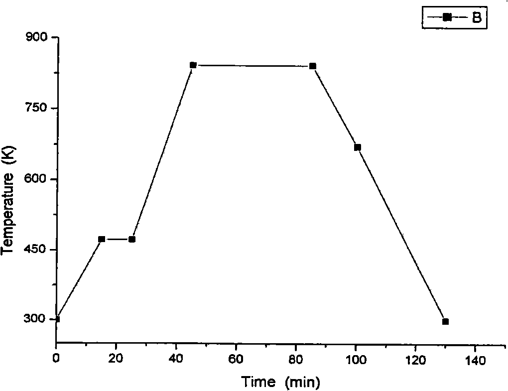
[0055] c. Thermal sintering treatment after printing

[0056] Heat up to 470K in the smart sintering furnace and keep it for 15 minutes, then raise the temper...


PUM


Abstract

The invention relates to field emission display field, particularly a method of preparing a nm Zno film by silk-screen printing and a luminotron using the same, characterized by comprising: a. preparing ZnO paste; b. preparing the ZnO film by the silk-screen printing; c. hot sinter process after printing; d. annealing after burning and mechanical post processing. The luminotron using the film is characterized by including two parallel ITO conducting glasses (1), which is sealed, also an insulating column (4) is arranged between the two parallel ITO conducting glasses (1); a phosphor powder film (3) is on the inner surface of one ITO conducting glass (1), and a ZnO film (5) is on other glass. ITO layers of the two ITO conducting glasses (1) are respectively educed on the outside of the luminotron. The method of preparing the nm Zno film by the silk-screen printing has low cost, and the ZnO film is printed evenly with large area. The luminotron using the film is high in stability, long in service life and high in luminous efficiency.

Description

technical field [0001] The invention relates to the field of field emission display (Field Emission Display, FED), in particular to a method for preparing a nanometer ZnO thin film by screen printing and a light-emitting tube using the thin film. Background technique [0002] ZnO is a wide bandgap semiconductor. Although the work function of ZnO is as high as 5.4eV, the one-dimensional ZnO nanostructure has a huge field enhancement factor, which makes the one-dimensional ZnO nanostructure also have excellent field emission characteristics. ZnO has negative electron affinity, high mechanical strength and chemical stability, and the study of ZnO nanostructures as electron emitters has become a hot spot in the international field. At present, there are many methods for preparing ZnO thin films, such as magnetron sputtering, metal organic chemical vapor deposition-MOCVD, molecular beam epitaxy-MBE, pulsed laser deposition (PLD) and laser molecular beam epitaxy (L-MBE), but these...

Claims


Application Information

Patent Timeline
Patent Type & Authority Applications(China)
IPC IPC(8): H05B33/10H05B33/12
Inventor 张秀霞
Owner BEIFANG UNIV OF NATITIES
Why Eureka
Try Eureka