Method for manufacturing miniature spring mechanical sensor for film performance test
A technology of spring mechanics and manufacturing method, which is applied in the process of producing decorative surface effects, microstructure technology, gaseous chemical plating, etc. Cutting precision limitation and other issues, to achieve the effect of rich structure, good linearity and long service life
- Summary
- Abstract
- Description
- Claims
- Application Information
AI Technical Summary
Problems solved by technology
Method used
Image

Examples
Embodiment 1
[0029] This embodiment 1 is implemented under the following conditions of implementation and technical requirements:
[0030] (1) On a 3-inch glass plate, sputter 1000 Titanium ( Figure 4 a), and at a temperature of 65°C, in 2% NaOH and 1% H 2 o 2 Oxidation treatment in the mixed solution for 3 minutes to form a uniform and dense black titanium oxide film layer ( Figure 4 b), to ensure a good bonding force with the photoresist;
[0031] (2) Then throw SU-8-50 type negative photoresist (supplier: Hong Kong Electronics; SU-8-50 is the model) on the titanium oxide film layer, and then perform pre-baking, slicing, exposure, intermediate Baking and development processing, according to the shape of the micro spring mechanical sensor designed by the mask, realize the patterning of its photoresist structure ( Figure 4 c);
[0032] (3) Using stack electroplating technology, on the treated titanium oxide layer, under the conditions of 50 ° C and pH 4.0, electroformed at a depo...
Embodiment 2
[0037] This embodiment 2 is implemented under the following conditions of implementation and technical requirements:
[0038] (1) Sputter 800 on a 4-inch glass sheet Titanium ( Figure 4 a), then repeat the oxidation treatment as in (1) step in Example 1 ( Figure 4 b);
[0039] (2) according to step (2) in embodiment 1, obtain the patterning ( Figure 4 c);
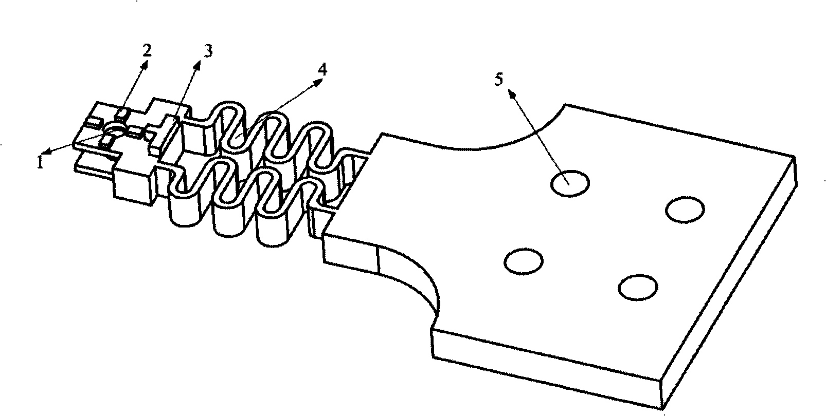
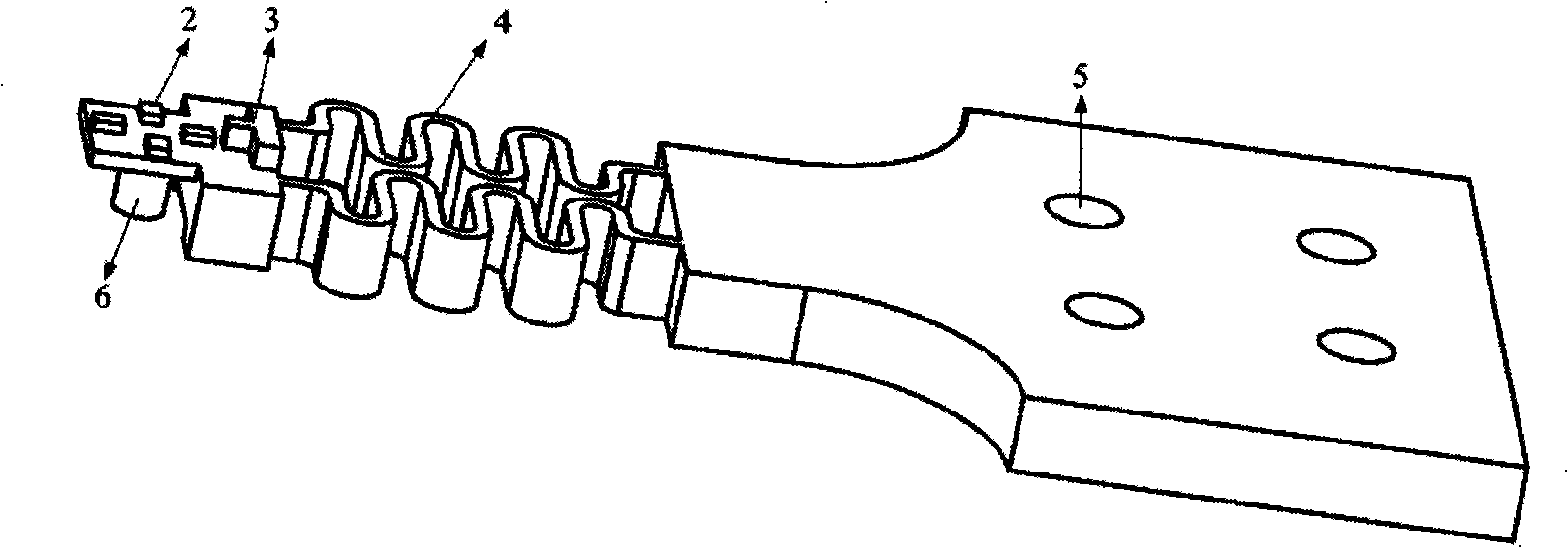
[0040] (3) according to the method of step (3) in embodiment 1, electroforming out figure 1 , image 3 Medium 1000μm Ni spring layer 4 and fixing hole 5, or figure 2Medium 1000μm Ni spring layer 4, fixing hole 5 and needle-shaped stretching head 6;
[0041] (4) according to the method for step (4) among the embodiment 1, the surface surface of the miniature spring mechanical sensor is carried out grinding, polishing treatment, carry out figure 1 , figure 2 centering mark 2 and displacement mark 3, or image 3 Graphicalization of mid-shift marker 3;
[0042] (5) According to the method of step (5) in embodim...
Embodiment 3
[0045] This embodiment 3 is implemented under the following conditions of implementation and technical requirements:
[0046] (1) On a 6-inch glass sheet, sputter 900 Titanium ( Figure 4 a), then repeat the oxidation treatment of step (1) in Example 1 ( Figure 4 b);
[0047] (2) according to the method of embodiment 1 step (2), obtain the patterning ( Figure 4 c);
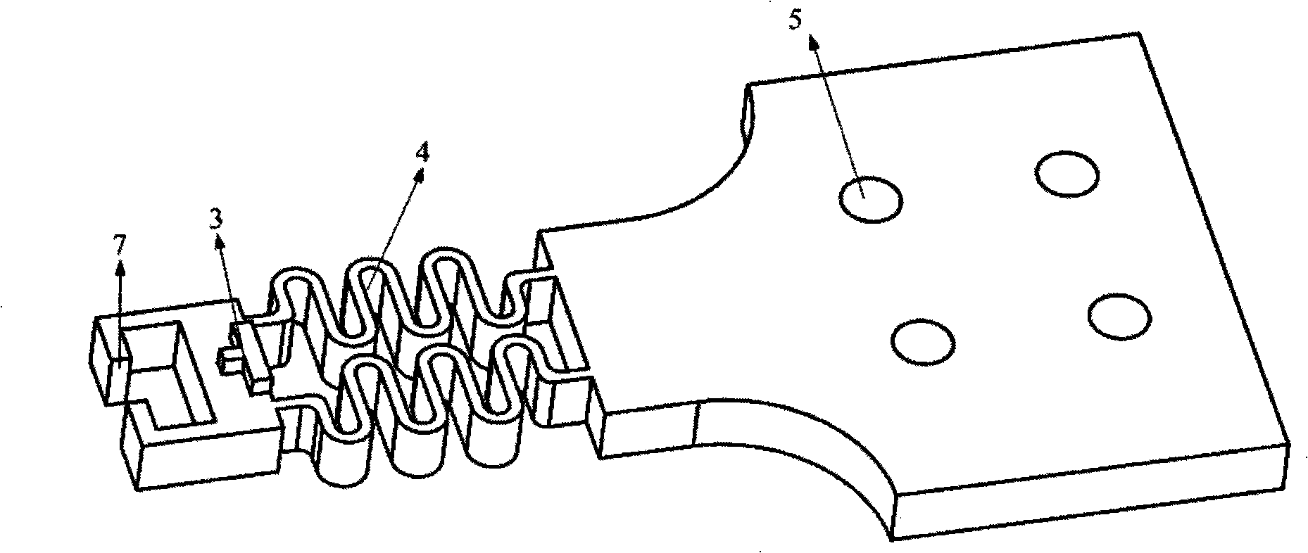
[0048] (3) according to the method of step (3) in embodiment 1, electroforming out figure 1 and figure 2 Medium 1500μm Ni spring layer 4 and fixing hole 5, or image 3 Medium 1500μm Ni spring layer 4, fixing hole 5 and rake-shaped stretching head 7;
[0049] (4) according to the method for step (4) among the embodiment 1, the surface surface of the miniature spring mechanical sensor is carried out grinding, polishing treatment, carry out figure 1 , figure 2 centering mark 2 and displacement mark 3, or image 3 Graphicalization of mid-shift marker 3;
[0050] (5) according to the method of step (5) ...
PUM
| Property | Measurement | Unit |
|---|---|---|
| Thickness | aaaaa | aaaaa |
| Thickness | aaaaa | aaaaa |
| Number of turns | aaaaa | aaaaa |
Abstract
Description
Claims
Application Information