

Electrolysis reactor for removing gaseous noxious pollutant from airflow and method of use thereof
An electrolytic reactor and pollutant technology, applied in chemical instruments and methods, separation methods, dispersed particle separation, etc., can solve problems such as troublesome solid-liquid separation process, and achieve the effect of low operating cost
- Summary
- Abstract
- Description
- Claims
- Application Information
AI Technical Summary
Problems solved by technology
Method used
Image

Examples
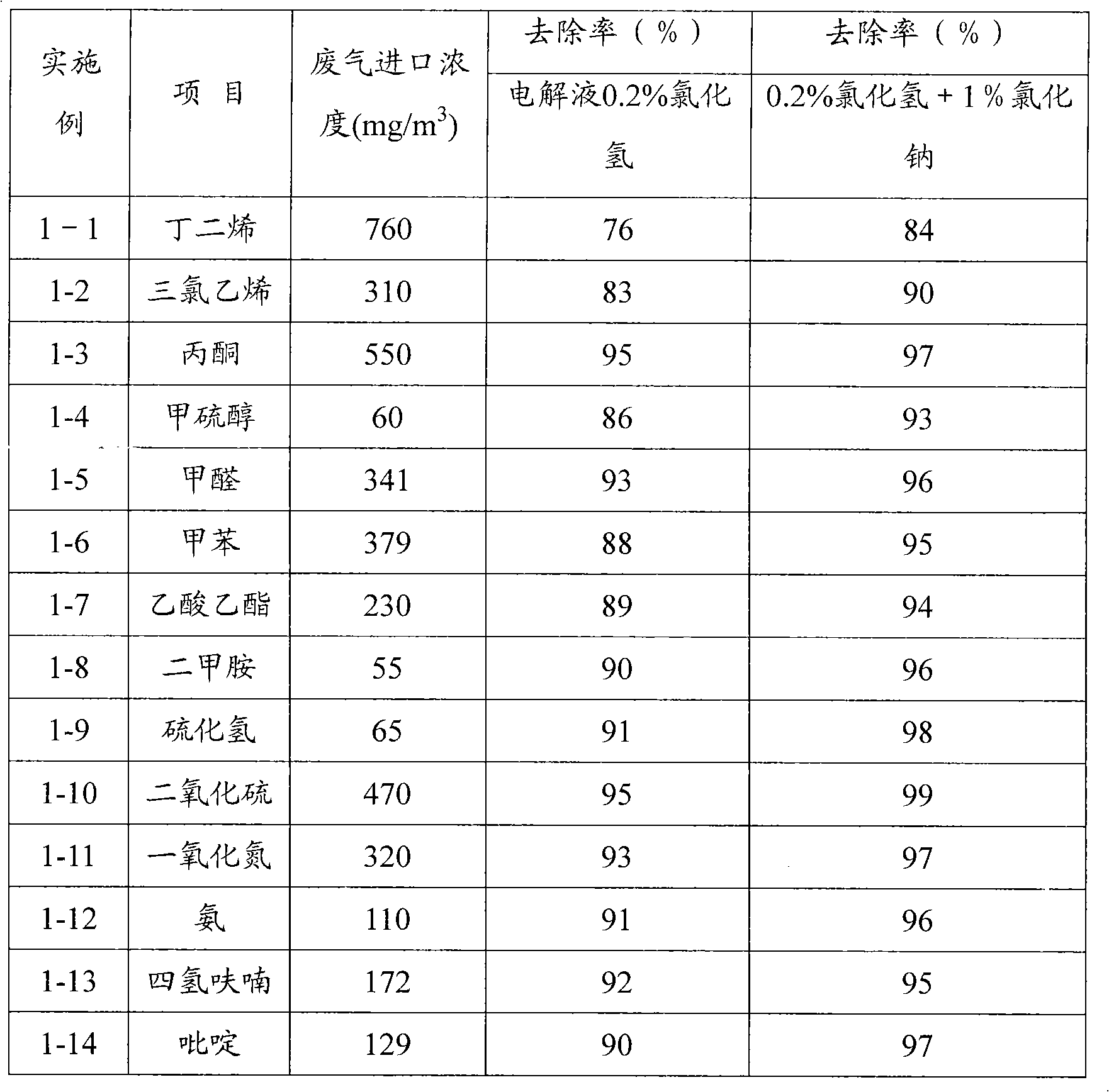
Embodiment 1
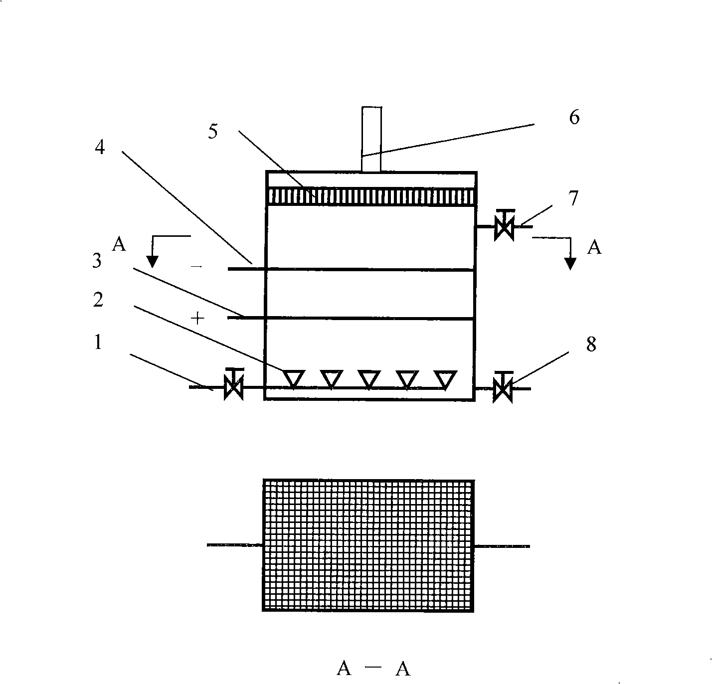
[0032] Experimental device: using figure 1 The reactor composed of 6 sets of superimposed electrode units is a cuboid vertical structure, the size of the reactor is 130mm×130mm×800mm, and the distance between the mesh electrode plates is 45mm. Mesh anode material is RuO 2 / Ti, the mesh cathode material is 316L stainless steel, the electrode thickness is 1mm, and the mesh is 5mm×12mm diamond-shaped holes.
[0033] Processing steps: Fill the electrolyte from the reactor liquid inlet 7, and then introduce the gas to be treated into the gas distributor 2 through the gas distributor 1 to be treated, and the gas to be treated is introduced into the reactor through the gas distributor 2, and then the gas to be treated is introduced into the reactor through the gas distributor 2, After a direct current or pulse current is applied to the cathode plate 4 and the anode plate 3, a redox reaction occurs in the reactor, and the gaseous harmful pollutants in the gas to be treated are conver...
Embodiment 2
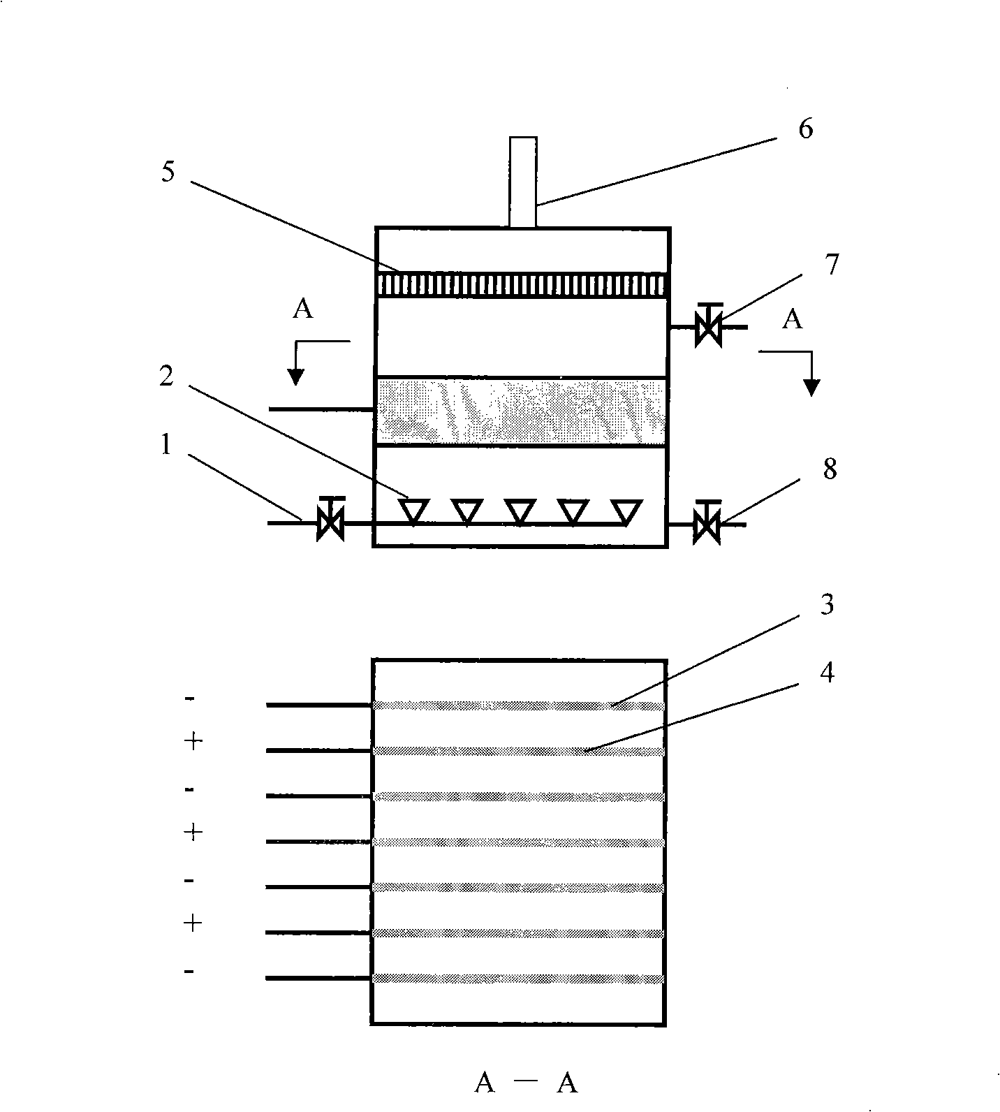
[0043] Experimental device: using figure 2 The shown reactor consists of 6 pairs of plate electrode units placed horizontally. The size of the reactor is 300mm×300mm×400mm, the size of the electrode plates is 130mm×130mm, and the distance between the plates is 40mm. Anode material is PbO 2 / Ti, the cathode plate material is titanium, and the electrode thickness is 1mm.
[0044] Processing steps: with embodiment 1.
[0045] Experimental conditions and parameters:
[0046] Electrolyte: 0.5% hydrogen chloride solution or a mixed solution of 0.5% hydrogen chloride solution and 5% sodium sulfate, the pH value of the solution is about 0.8 to 1.5. The liquid level is about 100mm above the highest electrode plate.
[0047] Power parameters: pulse power supply, peak current 15A, pulse frequency 50Hz.
[0048] Gas flow: 2000ml / min, gas temperature: 20°C
[0049] Gas composition to be treated: air + gaseous harmful pollutants
[0050] Experimental results: as shown in Table 2
...
PUM
 Abstract
Description
Claims
Application Information