Non-copious cooling lower carbon number hydrocarbons separation method containing light gas

A separation method and technology for low-carbon hydrocarbons, which are applied in the fields of oxide conversion to produce olefins and hydrocarbon cracking to produce olefins, and can solve the problems of high energy consumption and the like

Active Publication Date: 2009-01-28
WISON ENG
View PDF3 Cites 75 Cited by
  • Summary
  • Abstract
  • Description
  • Claims
  • Application Information

AI Technical Summary

Problems solved by technology

The energy consumption of such a large amount of

Method used


Image

  • Non-copious cooling lower carbon number hydrocarbons separation method containing light gas
  • Non-copious cooling lower carbon number hydrocarbons separation method containing light gas
  • Non-copious cooling lower carbon number hydrocarbons separation method containing light gas

Examples


Embodiment 1

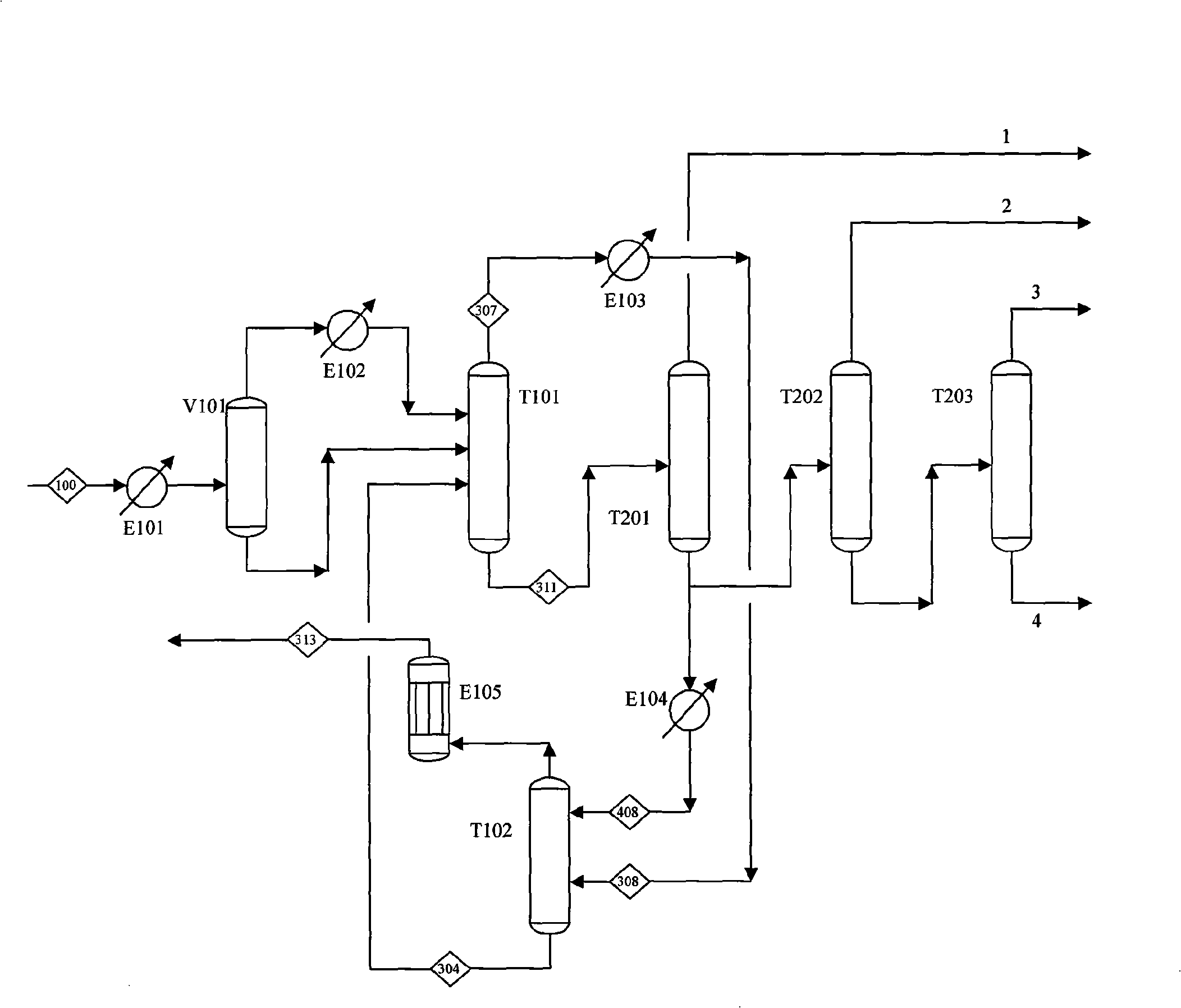
[0054] see process figure 1 , the outlet gas of a reactor enters the separation process after compression, water washing, alkali washing, removal of methanol and drying and dehydration. The gas S100 is cooled to about 10°C by the feed cooler E101 and enters the flash tank V101 for gas-liquid phase separation. The gas-liquid phase is further cooled to 0°C and -20°C by the feed cooler E102 of the pre-cutting tower respectively, and then enters the pre-cutting tower T101. The top product S307 of the pre-cutting tower T101 contains all light gases and ethylene accounting for about 24% of the feed. The output from the tower top enters the absorption tower T102 after being cooled by -60°C ethylene refrigerant in the feed cooler E103 of the oil absorption tower. Absorption tower T102 uses carbon three-based absorbent S408 to absorb carbon two in the feed. The gas at the top outlet of the absorption tower T102 is then cooled with -60°C ethylene refrigerant in the oil absorption tow...

Embodiment 2

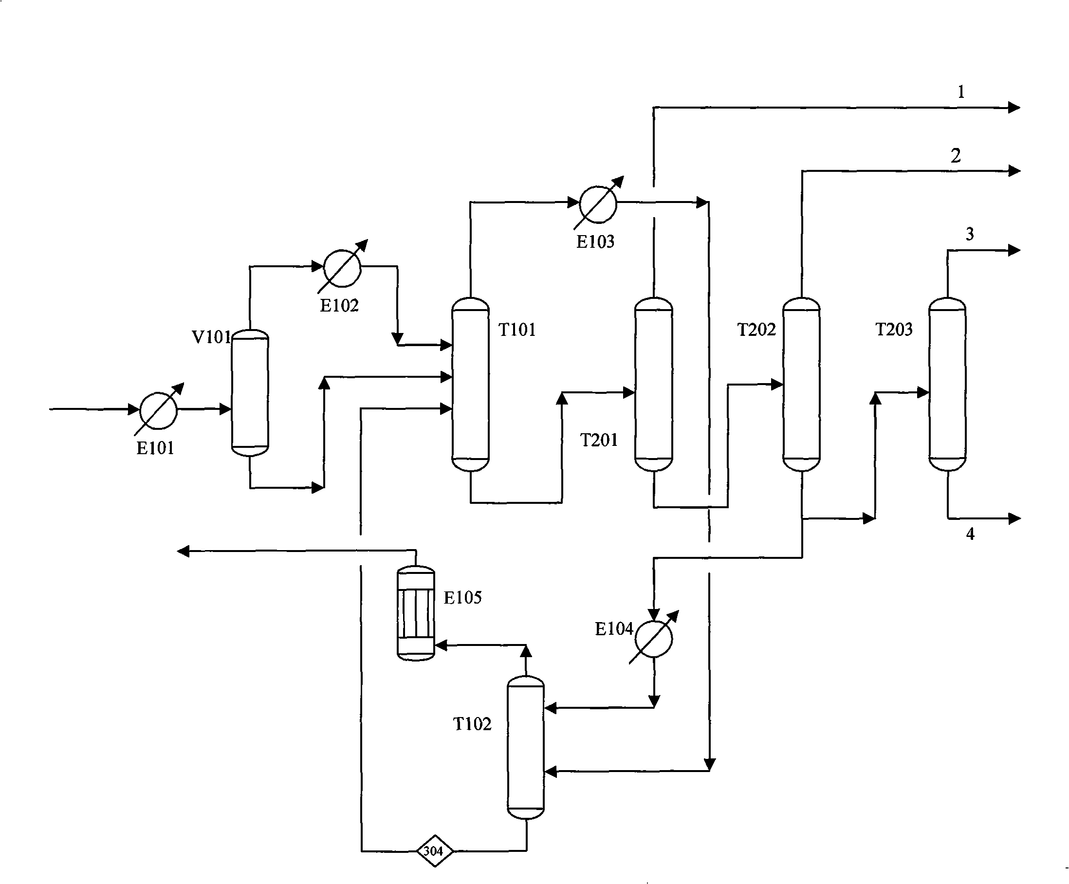
[0059] see process image 3, the outlet gas of a reactor enters the separation process after compression, water washing, alkali washing, removal of methanol and drying and dehydration. The gas S100 is cooled to about 10°C by the feed cooler E101 and enters the flash tank V101 for gas-liquid phase separation. The gas-liquid phase is further cooled to 0°C and -19°C by the feed cooler E102 of the pre-cutting tower respectively, and then enters the pre-cutting tower T101. The top product S308 of the pre-cutting tower T101 contains all light gases and ethylene accounting for about 27% of the feed, and enters the absorption tower T102 after being cooled in the feed cooler E103 of the oil absorption tower with -60°C ethylene refrigerant. The absorption tower T102 uses an absorbent (S408) with carbon five as the main component to absorb carbon two in the feed. The discharge S311 of the pre-cutting tower T101 tower kettle is C2, C3 and heavier products, which are directly sent to the...

Embodiment 3

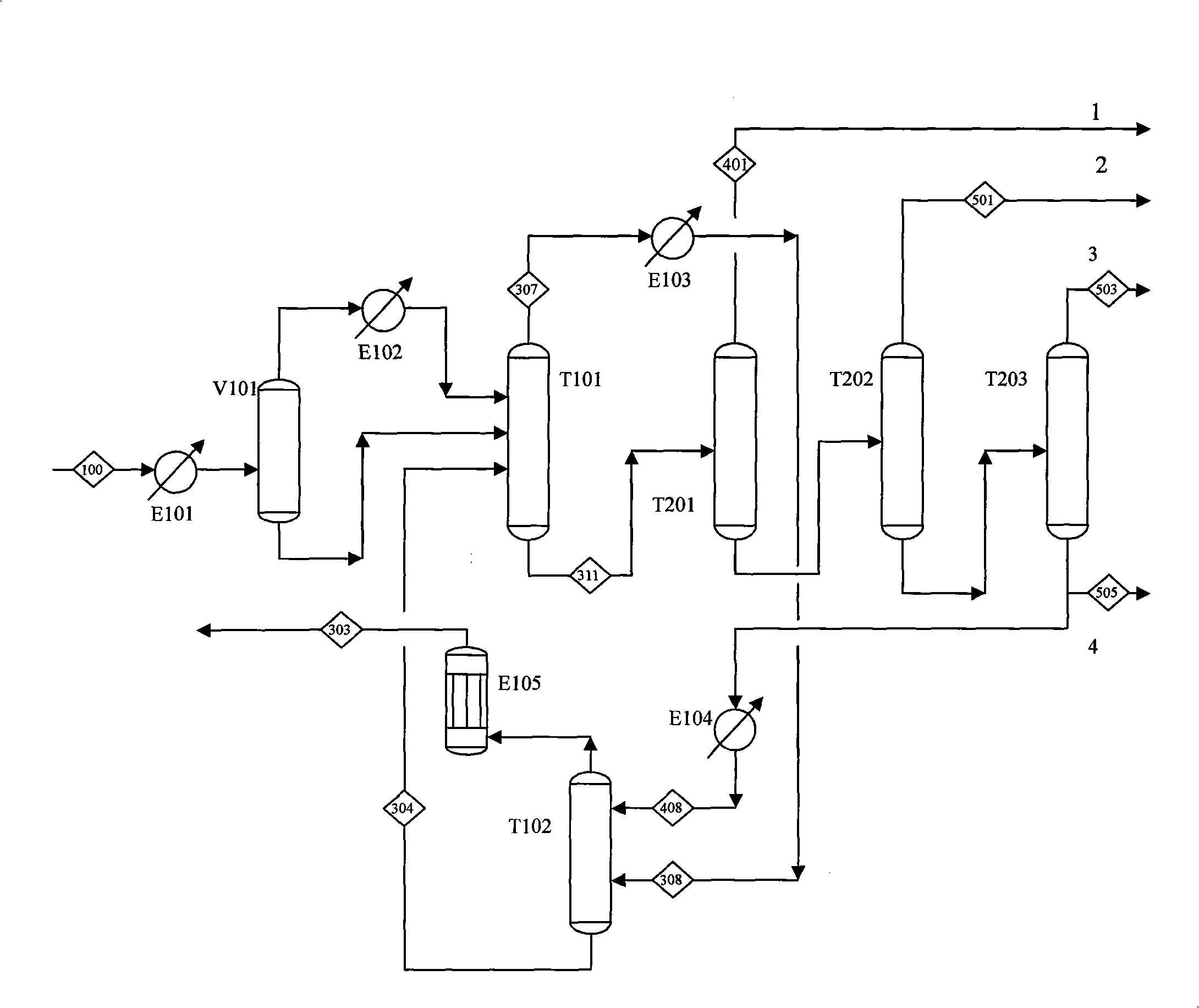
[0065] see process Figure 4 , the outlet gas S100 of a certain reactor enters the high-pressure depropanizer T202A after being compressed, washed with water, washed with alkali, dried and dehydrated. The top gas of the high depropanizer T202A is further pressurized to 3.6Mpa and then enters the acetylene hydrogenation reactor to remove alkynes. The material after removing acetylene is cooled to 2°C to obtain a gas-liquid two-phase, and the gas-liquid phase is further cooled separately. The gas phase enters the pre-cutting tower T101, and the liquid phase is divided into two parts, one part is used as the reflux of the high-pressure depropanizer T202A, and the other part is fed into the pre-cutting tower T101. The top product of the pre-cutting tower T101 is sent to the absorption tower T102 after cooling S308. The tower uses carbon three as an absorbent to absorb the carbon two hydrocarbons in the top product of the pre-cutting tower. The gas at the top of the absorption tow...


PUM


Abstract

The invention relates to a separation method for non-cryogenic low-carbon hydrocarbon containing light gases. The method comprise the steps as follows: (1) pre-treated gas at the outlet of a reactor is cooled to the temperature of 10-37 DEG C and sent to a pre-cutting tower; (2) a product at the top of the pre-cutting tower is cooled and sent to an absorption tower, and C2 hydrocarbons in the product at the top of the pre-cutting tower are absorbed by an absorbent consisting of C3, C4, C5 or the mixture of hydrocarbons thereof; and (3) tower kettle products of the pre-cutting tower are sent to a deethanizing column for clearly cutting the C2 and the C3 to obtain C2 distillate at the top of the tower; the tower kettle products are C3 and heavier components. Compared with the prior art, the method has the advantages of lower investment, lower energy consumption, higher recycling rate of materials, simpler operation, less maintenance workload, reliable operation, etc.

Description

technical field [0001] The invention belongs to the technical field of light hydrocarbon separation, and in particular relates to a separation method in the process of producing olefins by conversion of oxides and cracking of hydrocarbons to produce olefins. Background technique [0002] Ethylene and propylene are basic raw materials for the petrochemical industry and have historically been obtained by steam cracking or catalytic cracking of hydrocarbons. In the case of increasingly tight oil supply, people have developed the process of producing low-carbon olefins with oxides, especially methanol and ethanol as raw materials. Alcohols can be produced from natural gas or coal synthesis gas, thus avoiding the use of petroleum resources. [0003] The product composition of the oxide conversion process is similar to that of the cracking furnace outlet product composition of hydrocarbon cracking to ethylene, all of which are light gases such as hydrogen, nitrogen and light hydr...

Claims


Application Information

Patent Timeline
IPC IPC(8): C07C11/02C07C7/09C07C7/00
CPCC07C7/11
Inventor 倪进方李立新
Owner WISON ENG
Why Eureka
Try Eureka