Novel microwave oscillator driven by spinning current

A microwave oscillator, spin current technology, applied in resonators, waveguide devices, circuits, etc., can solve the problems of large injection current and external magnetic field, low microwave emission efficiency, low microwave transmission power, etc., and achieve high microwave power. Output, no external magnetic field, simple structure

Inactive Publication Date: 2009-02-04
TSINGHUA UNIV
View PDF0 Cites 12 Cited by
  • Summary
  • Abstract
  • Description
  • Claims
  • Application Information

AI Technical Summary

Problems solved by technology

The modulation range of the microwave oscillator based on the spin transfer effect reported in the literature can reach 1~200GHz, and the quality factor can reach more than 4000 [PRIBIAG V S, et al. "Magnetic vortex oscillator driven by d.c.spin-polarized current". NaturePhysics, 2007, 3(7): 498-503.], but before the practical application, there are still some key issues to be resolved
First of all, the power of microwave transmission is low, only on the order of nanowatts, which cannot meet the practical requirements; secondly, the efficiency of microwave emission is too low, requiring a large injection current and external magnetic field

Method used


Image

  • Novel microwave oscillator driven by spinning current
  • Novel microwave oscillator driven by spinning current
  • Novel microwave oscillator driven by spinning current

Examples


Embodiment Construction

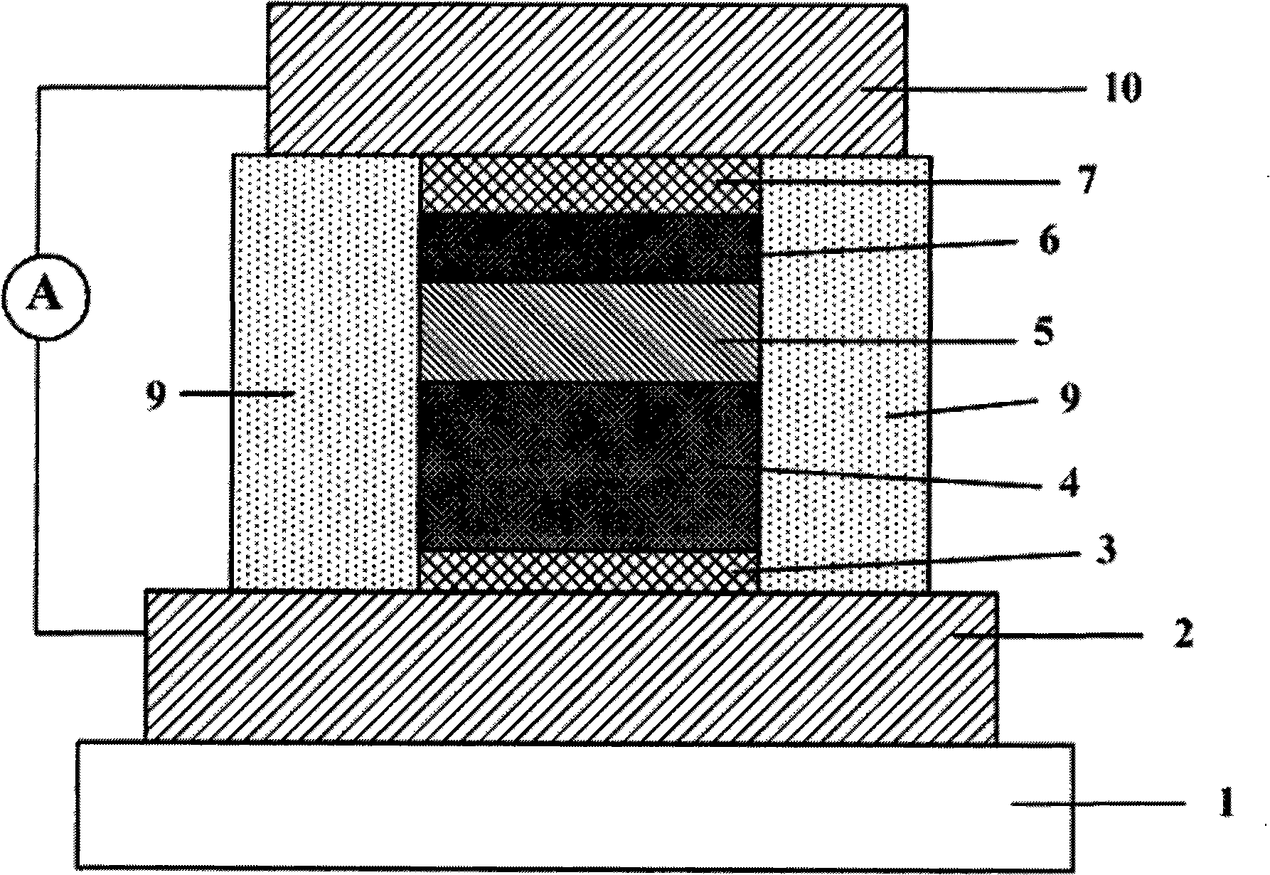
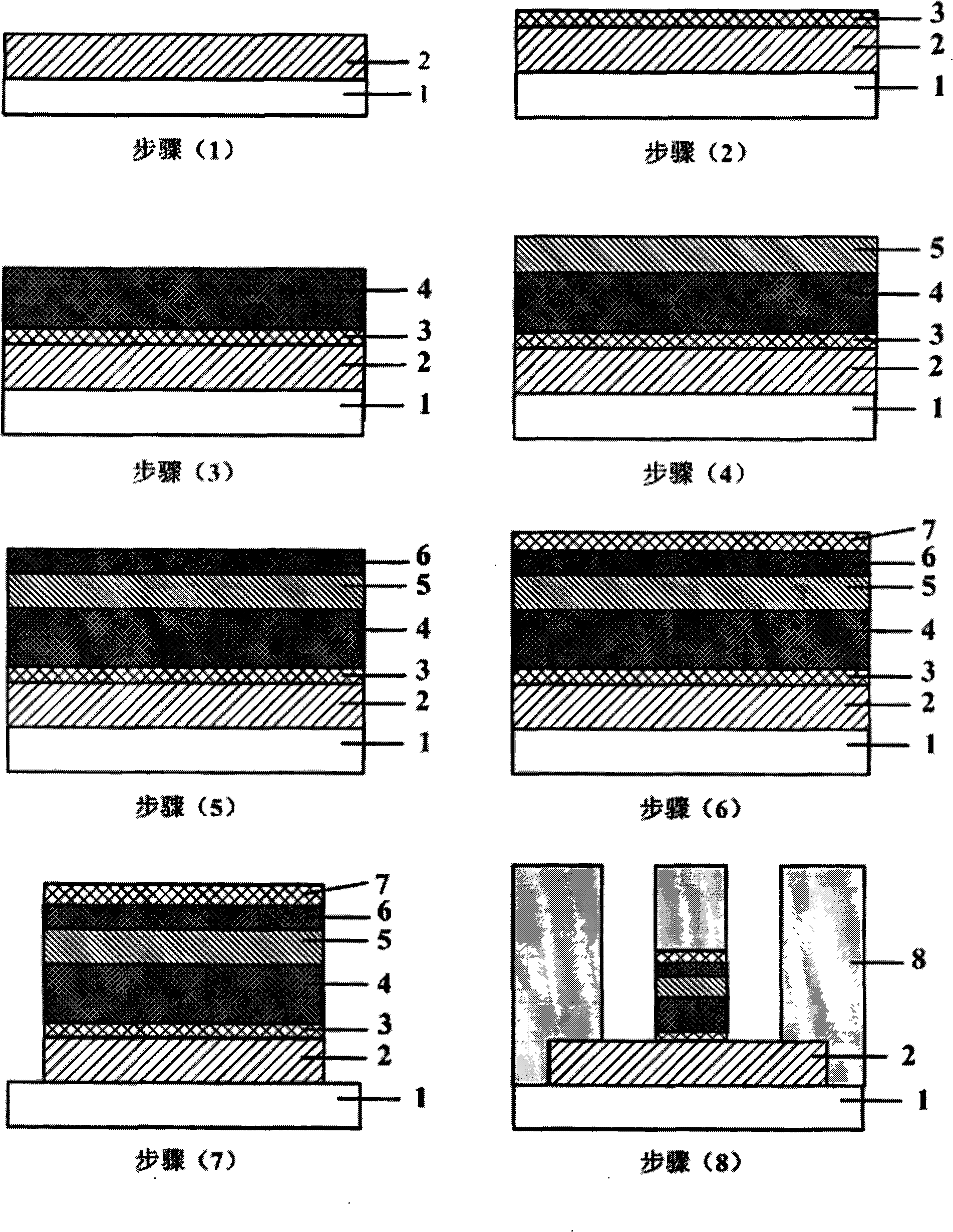
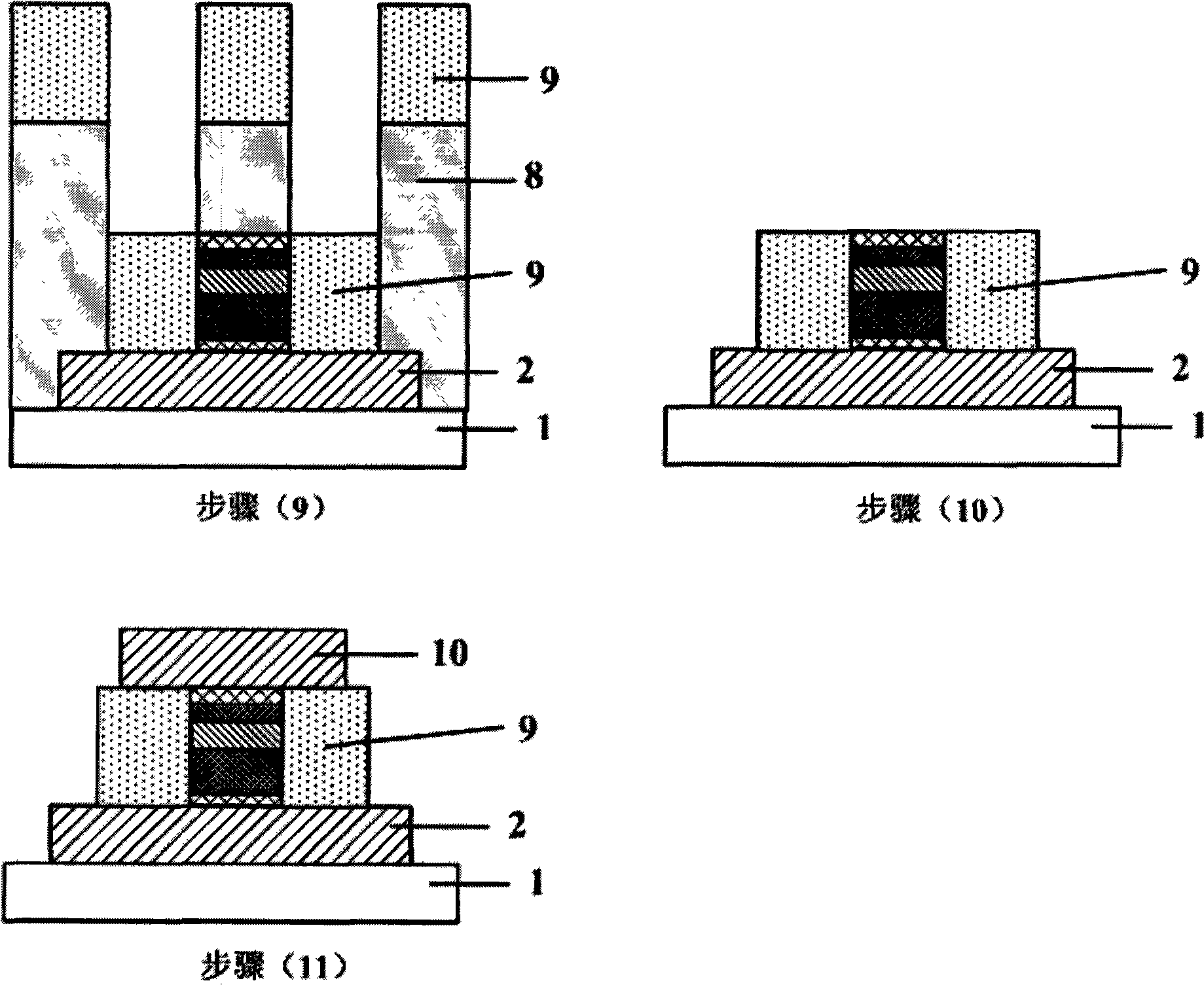
[0030] figure 2 It is a process flow diagram of the preparation method of the present invention. The structure is to first deposit the bottom electrode layer 2 on the silicon oxide substrate 1; then use the CMS-A six-target magnetron sputtering system of the American LESKER company to grow in sequence: the seed layer 3, the fixed layer 4, the isolation layer 5, The free layer 6 and the protective layer 7, wherein during the growth process of the fixed layer 4 and the free layer 6, the components of the magnetron sputtering equipment are used to apply an induced magnetic field, and the direction of the induced magnetic field is in the film plane and perpendicular to each other; and etching process to produce the bottom electrode pattern, and then use electron beam exposure and Ar ion beam etching to process the multilayer film structure on the bottom electrode 2 into a columnar structure with a lateral size of 100 ± 50 nanometers, and retain the photoresist 8; The insulating ...


PUM


Abstract

Disclosed is a spin-polarized current-driven microwave oscillator structure and a preparation method thereof, belonging to the field of spin transportation device technology, which is characterized in that an oxidized silicon substrate is adopted to prepare a multi-layer structure through the ultra-high vacuum magnetron sputtering, and then the multi-layer structure is processed into a columnar structure which has a horizontal size of 100+-50 nm through electron beam lithography, Ar ion beam etching, positive photoresist stripping and other microelectronics technologies. An upper electrode and a lower electrode are produced on the top layer of the multi-layer membrane structure and on the surface of the bottom-layer membrane, and the current injection direction is perpendicular to the plane of the metal multi-layer membrane. The invention has advantages that the initial magnetization directions of the fixed layer and the free layer are both located within the membrane plane and are perpendicular to each other, so that the free layer obtains the largest horizontal spin injection, so as to achieve substantial spin precession, to facilitate the obtaining of large microwave power output without any requirements of adding external magnetic field.

Description

technical field [0001] The invention belongs to the field of spin transport devices, in particular to the structure and preparation method of a novel microwave device based on the spin transfer effect. The device can be used in microwave communication and phase-locking technology and other fields. Background technique [0002] In recent years, spintronics has become a hot field of condensed matter physics due to its rich physical connotation and broad device application prospects. In 1996, scientists theoretically predicted a new spin-related effect at the nanoscale—the spin transfer effect, which injected new vitality into this field. Through the spin transfer torque between the injected spin-polarized current and the local electrons in the ferromagnetic layer, the magnetic moment of the ferromagnetic layer can be changed periodically, resulting in the magnetoresistance of the device changing with time. Change, generate alternating voltage, and obtain microwave power outp...

Claims


Application Information

Patent Timeline
Patent Type & Authority Applications(China)
IPC IPC(8): H01P7/00H01P7/10H01P11/00
Inventor 陈培毅任敏邓宁董浩张磊
Owner TSINGHUA UNIV
Why Eureka
Try Eureka