Beam detecting member and beam detector using it
A technology for detecting components and detectors, applied in radiation measurement, X/γ/cosmic radiation measurement, instruments, etc., can solve problems such as not being able to fully function, not being able to capture changes in cross-sectional distribution, not being able to radiate beam positions, etc.
- Summary
- Abstract
- Description
- Claims
- Application Information
AI Technical Summary
Problems solved by technology
Method used
Image

Examples
Embodiment 1
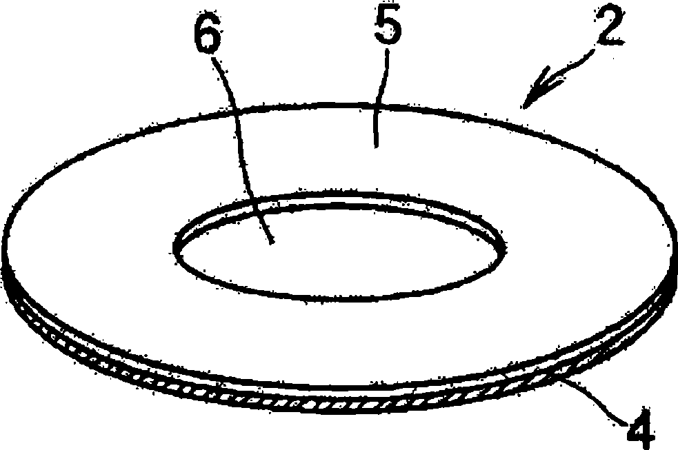
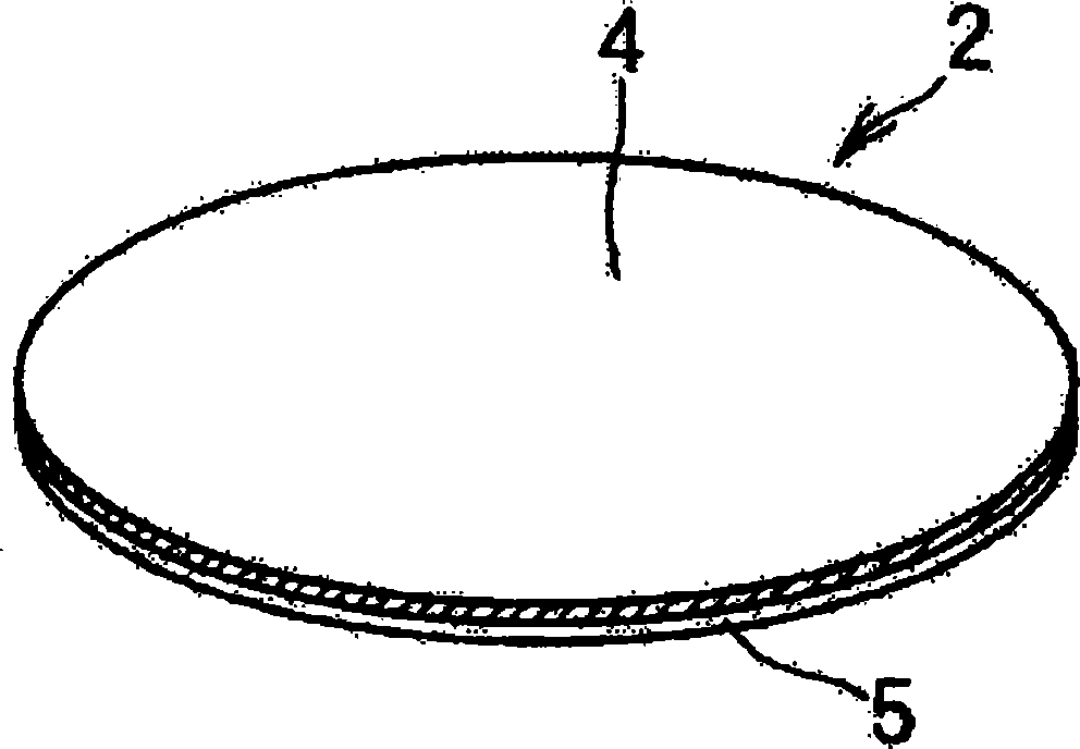
[0100] Made by the following process figure 1 , 2 The beam detection member 2 is shown. First, a silicon substrate with a diameter of 1 inch is subjected to ultrasonic waves in an ethanol-turbid solution of diamond powder having a diameter of several 10 μm, thereby performing a treatment to promote nucleation. After rinsing the diamond powder adhering to the substrate, the silicon substrate was set in a microwave plasma CVD apparatus to form a diamond film. As the source gas, a mixed gas of 1 vol % methane and 99 vol % hydrogen was used. The gas pressure was set to 45 Torr, and the substrate temperature was set to 800°C.
[0101] In order to mix Si into the above-mentioned polycrystalline diamond film, silane (SiH 4 ) or disilane (Si 2 h 6 ), the silicon wafer is arranged laterally along the silicon substrate. As a result, it took 8 to 30 hours to form a polycrystalline diamond film with a thickness of 10 to 40 μm. It was confirmed that 5 to 50 ppm of Si atoms permeat...
Embodiment 2
[0105] Boron-doped diamond was produced by the same process as in Example 1. In order to dope boron in the polycrystalline diamond film, diborane (B 2 h 6 ) or trimethylboron (B(CH 3 ) 3 ), boric acid is arranged laterally along the silicon substrate (B 2 o 3 )piece. As a result, a polycrystalline diamond film having a thickness of 15 to 48 μm was obtained by forming the film for 20 to 75 hours. The film is doped with 1 to 100 ppm of B atoms.
[0106] Using this boron-doped diamond sample, a part of the silicon substrate was etched in the same manner as in Example 1 to fabricate a beam detection member. When such a beam detection member was irradiated with an X-ray beam having an energy of 15 keV, cyan light emission was observed from the polycrystalline diamond film region at the irradiated position. In addition, when observation is performed after changing the dose of the irradiated X-ray beam, as shown in FIG. 7 , the brightness of the irradiated position is changed...
Embodiment 3
[0108] In the same manner as in Example 1, a polycrystalline diamond film in which Si, N, Li, Be, B, P, and S were mixed was synthesized in the polycrystalline diamond film constituting the beam detecting member. When these elements are doped into the polycrystalline diamond film, visible light to ultraviolet light emitted from the irradiation position can be confirmed by the energy of the emitted light. However, as shown in Table 1, the emission spectrum varies greatly depending on the type and concentration of the added elements.
[0109] Table 1
[0110] add element Addition method of elements in diamond film Luminous wavelength(nm) Si Add SiH to raw gas 4 or Si 2 h 6 516~539、738 N Add N to raw gas 2 or NH 3 389、415、516~539、575 Li Implanted Li ions 438 be Arrangement of metal Be on the substrate support table 516~539 B Add B to raw gas 2 h 6 443、516~539 P Add PH to raw gas 3 230、516~539 S Add H to the...
PUM
| Property | Measurement | Unit |
|---|---|---|
| Diameter | aaaaa | aaaaa |
| Thickness | aaaaa | aaaaa |
| Average particle diameter | aaaaa | aaaaa |
Abstract
Description
Claims
Application Information
 - R&D
- Intellectual Property
- Life Sciences
- Materials
- Tech Scout
- Unparalleled Data Quality
- Higher Quality Content
- 60% Fewer Hallucinations
Browse by: Latest US Patents, China's latest patents, Technical Efficacy Thesaurus, Application Domain, Technology Topic, Popular Technical Reports.
© 2025 PatSnap. All rights reserved.Legal|Privacy policy|Modern Slavery Act Transparency Statement|Sitemap|About US| Contact US: help@patsnap.com