

Erbium oxide hydrogen resistance coating and preparation thereof
An erbium oxide and coating technology, used in chemical instruments and methods, coatings, metal material coating processes, etc., can solve problems such as reducing stress and increasing bonding force, achieving good reliability, simple structure and process, and removal of Effects of unfavorable factors
- Summary
- Abstract
- Description
- Claims
- Application Information
AI Technical Summary
Problems solved by technology
Method used
Image

Examples
Embodiment 1
[0029] Example 1 Preparation of metal transition layer by radio frequency magnetron sputtering
[0030] The metal transition layer was prepared by radio frequency magnetron sputtering. First, CLAM is used as the matrix. Using ErFe with a diameter of 68mm 2 Target, the vacuum chamber is evacuated to 2.0×10 by mechanical pump and molecular pump in sequence -4 Pa. Then 20sccm of Ar gas is introduced, the sputtering pressure is adjusted to 0.5Pa, and the sputtering is carried out with a radio frequency power of 100W. The target base distance during sputtering is 55mm; when the substrate temperature is heated to 300°C, about 1 μm ErFe 2 transition layer.
Embodiment 2
[0031] Example 2 Preparation of Er by Reactive Radio Frequency Magnetron Sputtering 2 o 3 coating
[0032] Using pure Er target, using reactive radio frequency magnetron sputtering to prepare ErFe 2 Preparation of Er on the substrate of the transition layer 2 o 3 coating. Using the Er target with a diameter of 68mm, the vacuum chamber is evacuated to 2.0×10 by mechanical pump and molecular pump in sequence -4Pa. Then 20 sccm of Ar gas and 2 sccm of O 2 The mixed gas was used for reactive sputtering; the sputtering pressure was adjusted to 0.2Pa, and the RF power was 150W for sputtering. During sputtering, the target-base distance was 55mm, and the substrate heating temperature was 500°C. After 5 hours of sputtering, an Er of about 3 μm was obtained. 2 o 3 coating.
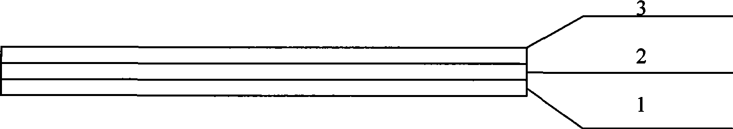
[0033] The structure of the prepared hydrogen barrier coating is as follows figure 1 shown. Among them, 1 is the base material; 2 is the metal transition layer prepared on the base material, in this case...
Embodiment 3
[0034] Embodiment 3 Measurement of resistivity of erbium oxide hydrogen barrier coating
[0035] At room temperature, the surface of the sample prepared in Example 2 and the steel substrate are used as two poles, different DC voltages are applied, the corresponding micro-current is measured, the insulation resistance is measured by the ratio of voltage / current, and the thickness and cross-sectional area of the sample are calculated. Calculate the insulation resistivity.
[0036] Measured Er 2 o 3 The relationship between the insulation voltage and current of the coating is shown in Table 1. Measuring electrode area 0.314cm 2 , the insulation resistance rate is 5.02×10 under the converted 120V voltage 13 Ωcm, it can be seen that the prepared Er 2 o 3 The hydrogen barrier coating has high insulation resistivity.
[0037] Table 1
[0038] Voltage / V 60 70 80 90 100 110 120 Current / nA 0.040 0.053 0.09 0.12 0.12 0.23 0.25
PUM
| Property | Measurement | Unit |
|---|---|---|
| Thickness | aaaaa | aaaaa |
| Area | aaaaa | aaaaa |
| Insulation resistivity | aaaaa | aaaaa |
Abstract
Description
Claims
Application Information