Electric tuning optical switch device

An optical switch and electrical tuning technology, applied in the direction of coupling of optical waveguides, to achieve the effects of easy fabrication, guaranteed coupling efficiency, and simple structure

Inactive Publication Date: 2009-07-15
NANJING UNIV OF POSTS & TELECOMM
View PDF1 Cites 6 Cited by
  • Summary
  • Abstract
  • Description
  • Claims
  • Application Information

AI Technical Summary

Problems solved by technology

[0008] Technical problem: The purpose of this invention is to propose an electrically tunable optical switch device structure to solve the electronic control tuning problem of the optical switch device

Method used


Image

  • Electric tuning optical switch device
  • Electric tuning optical switch device
  • Electric tuning optical switch device

Examples


specific Embodiment 1

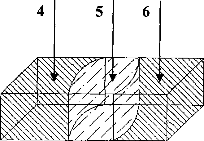
[0036] Take the planar 1×N optical splitter as an example. The Fluid Prism unit takes the form of a three-fluid (e.g. Figure 4 ), the conductive materials 9 and 12 on the left and right sides are Si, and a layer of 500nm SiO is oxidized on the surface of Si 2 as the insulating layer 13. The hydrophobic layer 14 is realized by dipping the hydrophobic agent FOTs. Conductive fluid 4 or 6 use saline solution,

[0037] But it may have freezing problem when used at low temperature. High concentration salt solutions can be used to lower the freezing point. In order to maintain the low density and refractive index of the brine, a low atomic weight salt is used: lithium chloride. Lithium chloride at a concentration of 20% results in a freezing point below -40°C, a density ρ of 1.12kg / m3, and a refractive index of 1.38. Insulating Fluid 5 uses a mixed phenylmethylsiloxane, which has a high refractive index and good electrowetting properties. Dissolve a few percent carbon tetrabr...

specific Embodiment 2

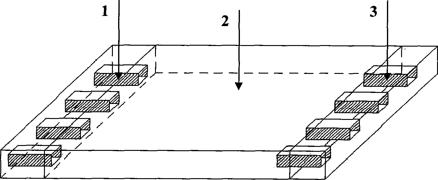
[0040] Take a planar N×N optical switch device as an example. The transparent substrate still uses a high-performance cover glass sputtered ITO film layer. The light input and output arrays are made of silicone rubber. The cavity storing the electrowetting prism material is coated with a conductive film, and the edges of the cavity are separated by insulating substances. The insulating layer is made of parylene with a thickness of 3 microns by vacuum coating. The hydrophobic layer is made of polytetrafluoroethylene polymer material (the English abbreviation is PTFE, and the trade name is Teflon). Teflon@AF) coating to achieve. The insulating fluid is bromododecane (density 1.0399, refractive index 1.4583), and the conductive fluid is saline solution with the same density to remove the influence of gravity. The voltage controls the shape of the interface between the insulating fluid and the conductive fluid to adjust the shape and position of the liquid prism, thereby adjus...

specific Embodiment 3

[0042] Take the three-dimensional M×M optical switch device as an example. Other manufacturing processes can adopt the method of embodiment 1 or embodiment 2 to carry out. If the cavity adopts a cylindrical structure, its electrode cross-section can be Figure 15 The 4-electrode structure or the 6-electrode structure in Figure 16.


PUM


Abstract

An electric tuning optical switch device relates to a light switch device structure composed of an electric control fluid prism based on electric moisture effect, the switch device has a fluid prism light input array (1) and a fluid prism light output array (3) with rectangle or cylinder units, the space between the two arrays is formed into a light exchanging space (2); when the voltages are applied on between a left front power supply (15) and a left rear power supply (16), and between a right front power supply (18) and a right rear power supply (17), the interfacial tension between the conductive fluid and the side walls (19, 20) is reduced because of the electric moisture effect, thereby changing the fluid interface shapes and implementing the adjustment of the composition of the lens prism and shapes thereof, further implementing the regulation and control of the light deflection angle, the light exchanging electric control purpose can be reached by the input/output liquid prism array. The four sets of power supply voltages of light input prism unit and the corresponding light output prism unit are respectively kept for consistence to ensure the input/output light coupling.

Description

technical field [0001] The invention relates to a novel electrical tuning optical switch device structure and its working principle, and belongs to the technical field of optical communication, photoelectric sensing and optical information processing devices. Background technique [0002] The optical switch is the core device of optical switching, and it is also one of the main factors affecting the performance of the optical network. As a key device of the new-generation all-optical networking network, the optical switch is mainly used to realize functions such as routing selection, wavelength selection, optical cross-connection and self-healing protection on the optical level. In an all-optical network, optical add-drop multiplexing devices (OADM) and optical cross-connects (OXC) are indispensable network node devices, and optical switches and optical switch arrays are the core devices in these devices. With the continuous progress of understanding and research on device ...

Claims


Application Information

Patent Timeline
Patent Type & Authority Applications(China)
IPC IPC(8): G02B6/32
Inventor 陈陶梁忠诚徐宁赵瑞毕岚李培丽李建林
Owner NANJING UNIV OF POSTS & TELECOMM
Why Eureka
Try Eureka