Sewage sludge drying method and drying machine

A drying machine and sludge technology, applied in the direction of dehydration/drying/concentrated sludge treatment, etc., can solve the problems of low heat exchange efficiency of hot air, low air thermal conductivity, increased energy consumption of blasting, etc., and achieve sludge drying Good drying effect, less heat loss, and less heat loss

Inactive Publication Date: 2009-08-19
ZHEJIANG HUAZHANG TECH
View PDF3 Cites 22 Cited by
  • Summary
  • Abstract
  • Description
  • Claims
  • Application Information

AI Technical Summary

Problems solved by technology

[0006] Hot air drying has the following defects: 1. Due to the low thermal conductivity of air, the thermal efficiency of hot air heat exchange is not high
2. In order to improve the efficiency of hot air drying, technical solutions such as increasing wind speed, increasing air volume, and hot air recycling are generally adopted. The implementation of these solutions will inevitably lead to increased blast energy consumption and increased heat loss, which is not conducive to energy conservation
3. The operating temperature of hot air drying is always high. If the material is flammable, there will be a safety hazard; if the material contains volatile pollution factors, it will easily cause secondary pollution
4. If the flue gas is used as the heat source, it will break the balance of the working conditions of the boiler, and the coal consumption will increase in order to ensure the temperature of the flue gas

Method used


Image

  • Sewage sludge drying method and drying machine
  • Sewage sludge drying method and drying machine

Examples


Embodiment approach 1

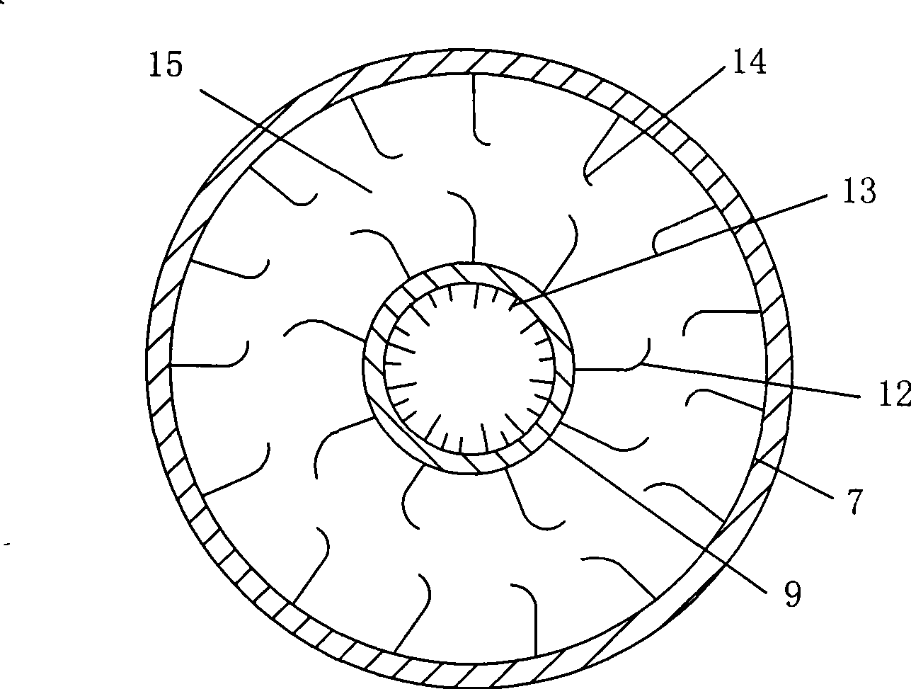
[0029]Embodiment Scheme 1, the sludge is placed in the inner drum, the heat source is placed in the interlayer between the inner drum and the outer drum, so that the heat source is surrounded by the sludge, and the heat of the heat source is transferred from the outside to the inside of the inner drum through the wall of the inner drum. Sludge inside; embodiment 2, put the heat source in the inner drum, put the sludge in the interlayer between the inner drum and the outer drum, the sludge surrounds the heat source in the middle, and the heat of the heat source is transferred from the inside to the outside through the inner drum wall To the sludge placed in the interlayer between the inner drum and the outer drum. Option 1 has a higher sludge drying temperature and a faster sludge drying speed, while Option 2 has a larger drying capacity than Option 1.

[0030] Refer to the attached drawings for the structure of the embodiment of the sludge dryer of the present invention.

Embodiment 1

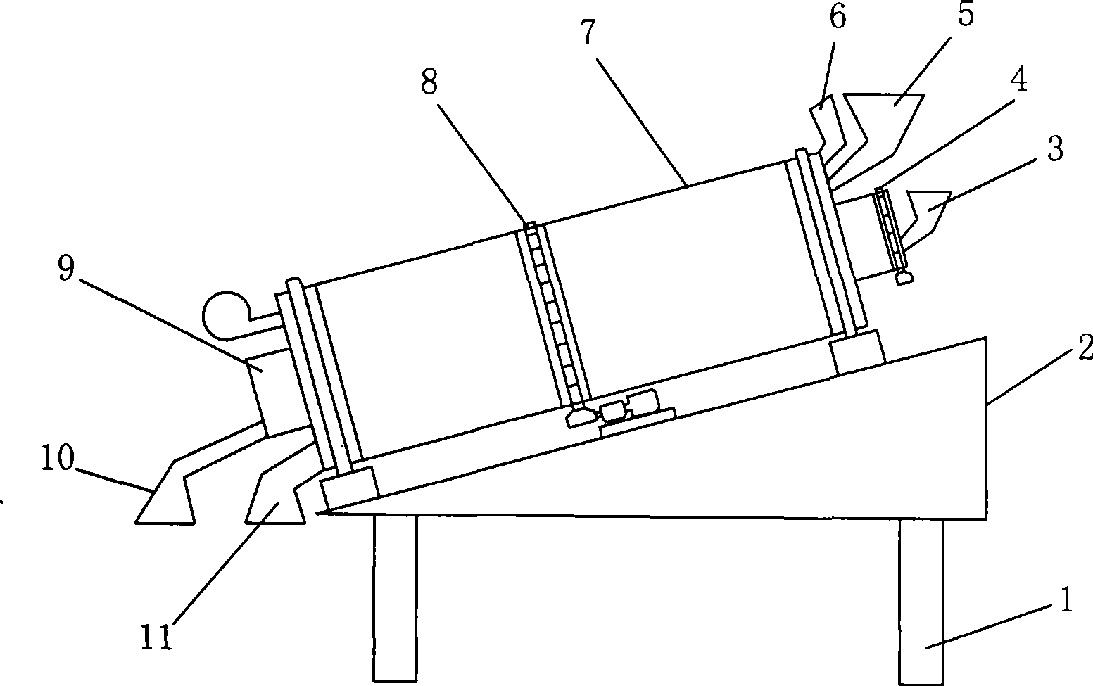
[0032] see figure 1 , The sludge dryer in this embodiment is a rotary drum dryer using incineration tailings as a heat source, including a frame 1, a support mechanism 2, an outer drum 7, an inner drum 9, a lifting mechanism and a driving device. The outer drum 7 is fixed on the supporting mechanism 2, the supporting mechanism 2 is fixed on the frame 1, the inner drum 9 is located in the middle of the outer drum 7, the lifting mechanism is located between the outer drum 7 and the inner drum 9, and the outer drum 7 is driven by 2# Driven by device 8, inner drum 9 is driven by 1# drive device 4. The driving devices of the outer drum 7 and the inner drum 9 can be arranged separately or combined into one.

[0033] A height adjustment mechanism is set on the frame 1. According to the length of drying time required for the moisture content of the sludge in drying treatment, the height of both sides of the frame 1 is adjusted through the height adjustment mechanism to realize the ad...

Embodiment 2

[0038] The height adjustment device for adjusting the inclination angle of the outer drum 7 and the inner drum 9 of the sludge dryer in this embodiment is provided on the supporting mechanism 2 . During use, according to the drying time required by the dried sludge, the inclination angle of the outer drum 7 and the inner drum 9 set together is adjusted through the height adjustment device. Other structures and uses of this embodiment are the same as in Embodiment 1.


PUM


Abstract

The invention discloses a sludge drying method and a drying machine. The sludge drying method is used to dry the sludge through the afterheat from the burning of tailings. The sludge drying method adopts a drum type drying machine in which an inner drum is sleeved with an outer drum. The method comprises the following steps: putting a heat source and the sludge respectively in the inner drum or in an interlayer between the inner drum and the outer drum; rotating the inner drum and the external drum so as to make the heat source and the sludge in the inner drum or in the interlayer between the inner drum and the outer drum roll continuously; and transferring the heat of the heat source evenly to the sludge through the wall of the inner drum so as to dry the sludge. The sludge drying machine comprises a machine frame, a supporting mechanism, the inner drum, the outer drum and a driving device, wherein the outer drum is arranged on the machine frame through the supporting mechanism; the inner drum is positioned in the middle of the outer drum; the driving device respectively drives the outer drum and the inner drum to rotate; an outer material inlet and an outer material outlet are arranged at the two ends of the outer drum respectively; and an inner material inlet and an inner material outlet are arranged at the two ends of the inner drum respectively. The sludge drying method is scientific and practical and brings about high thermal efficiency; and the sludge drying machine has a reasonable structure and low drying cost.

Description

technical field [0001] The invention relates to a drying method and equipment, in particular to a sludge drying method and a dryer which use various incineration tailings as heat sources and use the waste heat of the incineration tailings to dry sludge. Background technique [0002] Chinese Patent Publication No. CN1398336 "Method and Procedure for Co-combustion of Waste-to-Energy Equipment" discloses that a device consisting of a waste receiving and processing system, a waste co-combustion system, and a pre-calciner is used to integrate cement. A co-combustion method for the production and incineration of municipal solid waste, which involves sending the hot gas generated during the cooling of the clinker to a rotary furnace and drying the solid waste in a rotary dryer. In this method, the unfavorable materials used in the cement process produced by waste incineration are bypassed to the scrubber system and cement kiln, so that the residual slag of the waste kiln is process...

Claims


Application Information

Patent Timeline
Patent Type & Authority Applications(China)
IPC IPC(8): C02F11/12
Inventor 唐志超赖圣卿
Owner ZHEJIANG HUAZHANG TECH
Why Eureka
Try Eureka