Laminated structure of amorphous silicon solar battery and dye sensitization battery

A dye-sensitized battery, solar cell technology, applied in capacitor electrodes, capacitor electrolytes/absorbers, circuits, etc., can solve the problem of low photoelectric conversion efficiency of batteries, and achieve the effects of low price, improved conversion efficiency, and simple production process

Inactive Publication Date: 2009-08-19
上海拓引数码技术有限公司
View PDF0 Cites 11 Cited by
  • Summary
  • Abstract
  • Description
  • Claims
  • Application Information

AI Technical Summary

Problems solved by technology

[0006] The technical problem to be solved by the present invention is: to overcome the problem that the photoelectric conversion efficiency of the battery is not high

Method used


Image

  • Laminated structure of amorphous silicon solar battery and dye sensitization battery
  • Laminated structure of amorphous silicon solar battery and dye sensitization battery
  • Laminated structure of amorphous silicon solar battery and dye sensitization battery

Examples


Embodiment 1

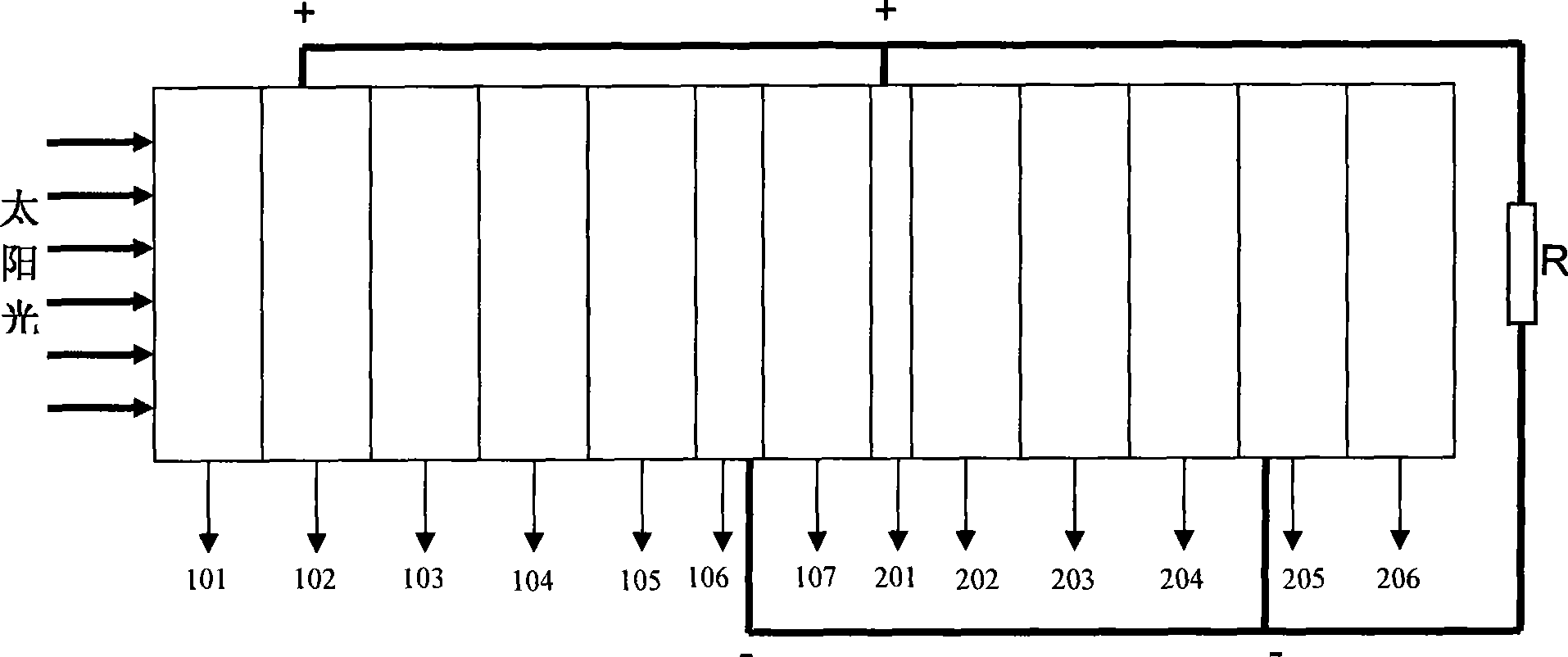
[0049] image 3 It is a schematic diagram of the structure of the amorphous silicon solar cell and the dye-sensitized laminated cell of the present invention, including the top amorphous silicon solar cell 1 that can absorb short-wave high-energy sunlight and the bottom dye-sensitized absorbing long-wave low-energy sunlight battery 2. Amorphous silicon solar cell 1 is composed of outermost transparent substrates 101 and 107, second outer transparent conductive oxide layers 102 and 106, and amorphous silicon semiconductor layers 103-105, including amorphous silicon semiconductor P layer 103, an amorphous silicon semiconductor I layer 104, and an amorphous silicon semiconductor N layer 105. The dye-sensitized cell 2 is composed of a counter electrode, a semiconductor sensitized photoanode located at the bottom, and an electrolyte 203 located between the two electrodes. The counter electrode is composed of a transparent conductive oxide layer 201 and a platinum catalyst layer 2...

Embodiment 2

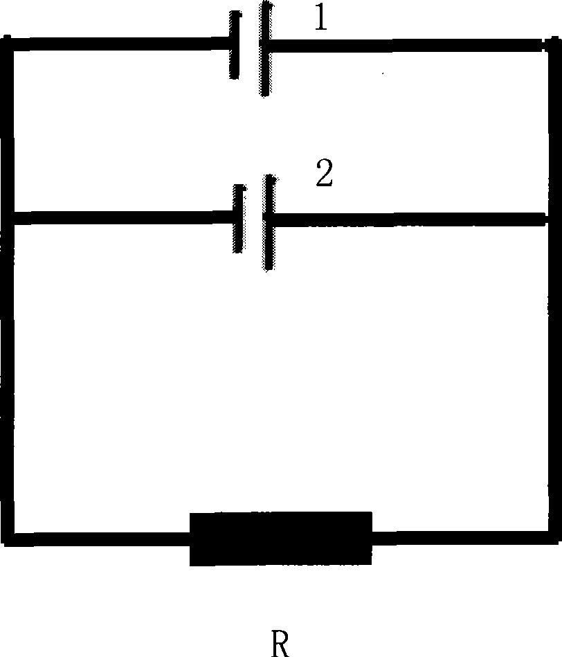
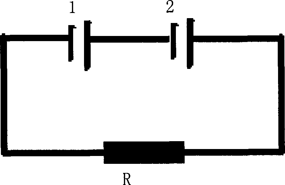
[0053] The basic structure includes an amorphous silicon solar cell 1 on the top and a dye-sensitized solar cell 2 on the bottom. Change the adsorption amount of the dye in the dye-sensitized cell, so that the short-circuit current of the dye-sensitized cell and the amorphous silicon solar cell are basically similar, and the current matching is realized, such as Figure 4 As shown, the amorphous silicon solar cell and the dye-sensitized cell are connected in series, that is, the transparent conductive oxide layer 102 of the amorphous silicon solar cell is used as the positive external circuit, and the transparent conductive oxide layer 106 of the amorphous silicon solar cell is (negative electrode) connected to the transparent conductive oxide layer 201 (positive electrode) of the dye-sensitized cell, figure 2 yes Figure 4 From the equivalent circuit diagram, it can be seen that the two batteries are connected in series, and the transparent conductive oxide layer 205 of the...

Embodiment 3

[0056] The basic structure includes an amorphous silicon solar cell 1 on the top and a dye-sensitized solar cell 2 on the bottom. Change the dye adsorption amount of the dye-sensitized cell to achieve current matching between the two cells, and connect the amorphous silicon solar cell and the dye-sensitized cell in series, that is, the negative electrode of the amorphous silicon solar cell is connected to the negative electrode of the dye-sensitized cell. Positive pole, the positive pole external circuit of the amorphous silicon solar cell, and the negative pole external circuit of the dye-sensitized battery. Wherein, there is no transparent conductive glass barrier (107 in embodiment 1) between the N layer 105 of the P-I-N layer of the amorphous silicon solar cell and the catalyst layer 202 of the dye-sensitized cell, but is directly connected through a layer of buffer layer 3, such as Figure 5 and Figure 6 As shown, a platinum catalyst layer 202 is attached to the buffer ...


PUM


Abstract

The invention relates to an amorphous silicon solar cell and dyestuff sensitized cell laminated structure which comprises an amorphous silicon solar cell positioned at the top and used for absorbing high-energy sunlight with biased shortwave, and a dyestuff sensitized cell positioned at the bottom and used for absorbing low-energy sunlight with biased long-wave, wherein, the amorphous silicon solar cell and the dyestuff sensitized cell are connected in series or in parallel; the amorphous silicon solar cell and dyestuff sensitized cell laminated structure can achieve the following effects: the dyestuff sensitized cell can be used for adsorbing close infrared light; the designed laminated cell is characterized by simple manufacturing technique and low price; the problem that the conventional solar cell has low photoelectric transformation efficiency and narrow solar energy absorbing spectrum can be solved; and the structure can increase the utilization rate of sunlight to the greatest extent, improve transformation efficiency and reduce light energy loss.

Description

technical field [0001] The invention relates to a laminated structure of an amorphous silicon solar battery and a dye-sensitized battery. Background technique [0002] Solar energy is an inexhaustible energy source that does not pollute the environment and is safe to use. Solar photovoltaic power generation has the advantages of no noise, no pollution, no geographical restrictions, no consumption of materials, and easy storage. [0003] Solar power generation is a high-end technology that converts solar energy into electrical energy. Its development has gone through stages such as monocrystalline silicon cells, polycrystalline silicon cells, and amorphous silicon thin-film cells. Amorphous silicon thin-film solar cells have made many new breakthroughs and new achievements in the development of solar cells. Compared with monocrystalline silicon solar cells, they have many remarkable features of their own. First of all, the production cost is low, the price of raw materials ...

Claims


Application Information

Patent Timeline
Patent Type & Authority Applications(China)
IPC IPC(8): H01G9/20H01G9/022H01G9/04H01L31/042H01M14/00
CPCY02E10/542Y02P70/50
Inventor 包健陈徽夏芃范振华范继良
Owner 上海拓引数码技术有限公司
Why Eureka
Try Eureka