Laser differential confocal spectrum microscopy tomography device

A differential confocal and tomographic imaging technology, applied in measurement devices, material excitation analysis, optics, etc., can solve problems such as poor geometric position detection ability, difficulty in accurately capturing focus O-excited Raman spectroscopy, diffraction limit limitation, etc. Achieve the effect of improving absolute measurement, micro-spectral and geometric position detection capabilities

Inactive Publication Date: 2009-09-09
BEIJING INSTITUTE OF TECHNOLOGYGY
View PDF0 Cites 31 Cited by
  • Summary
  • Abstract
  • Description
  • Claims
  • Application Information

AI Technical Summary

Problems solved by technology

[0003] Confocal microscopes are widely used in cutting-edge disciplines and fields such as biomedicine, materials science, and high-energy physics because of their spectral tomography capabilities, and because of their high resolution, they can perform fine imaging of living biological samples and tiny industrial products , providing the microscopic geometrical information and material spectral information of the sample, it has become a powerful tool for medical observation and manufacturing inspection; however, to improve the micro-region detection capability of the confocal Raman spectroscopy microscope system, it is necessary to accurately determine the sample focus, so that the sample is located near the focal point O, but the response sensitivity of the confocal microscope characteristic curve near the focal point O is extremely low. The ability to detect the "geometric position of the region" cannot

Method used


Image

  • Laser differential confocal spectrum microscopy tomography device
  • Laser differential confocal spectrum microscopy tomography device
  • Laser differential confocal spectrum microscopy tomography device

Examples


Example Embodiment

[0028] The present invention will be further described below with reference to the drawings and embodiments.

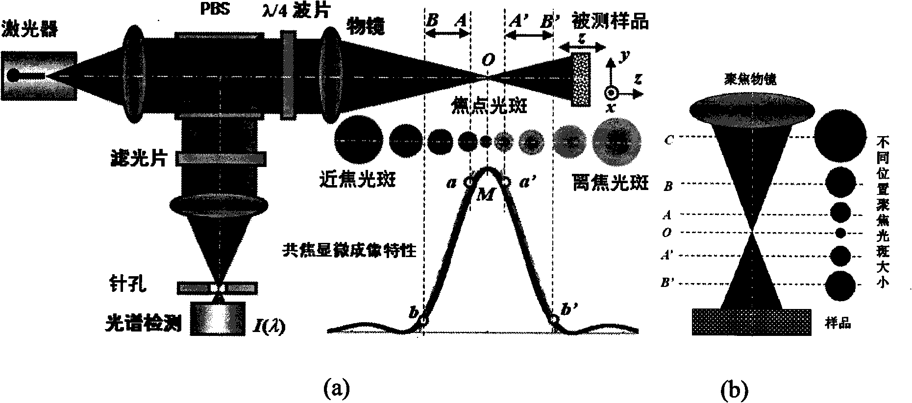
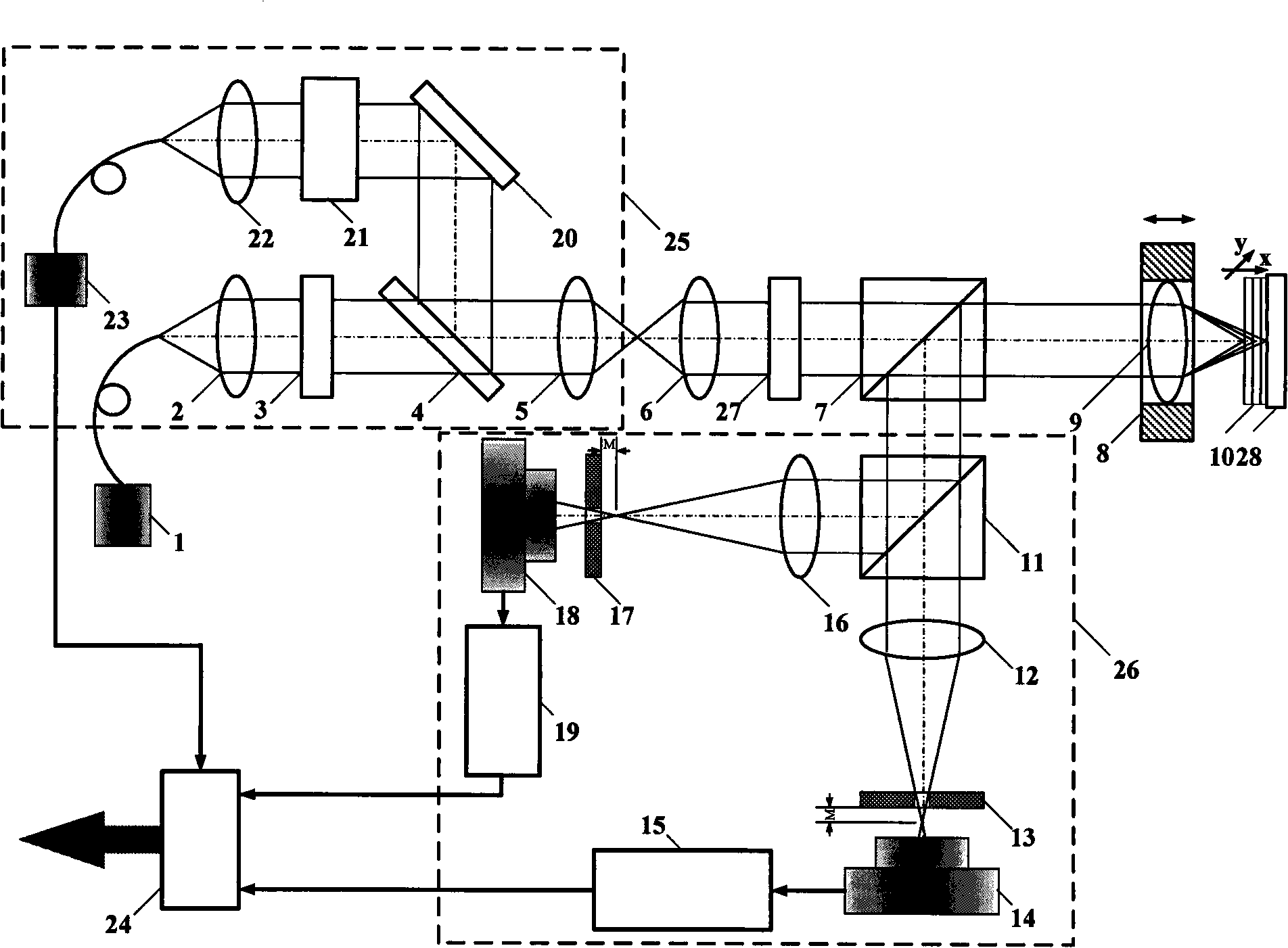
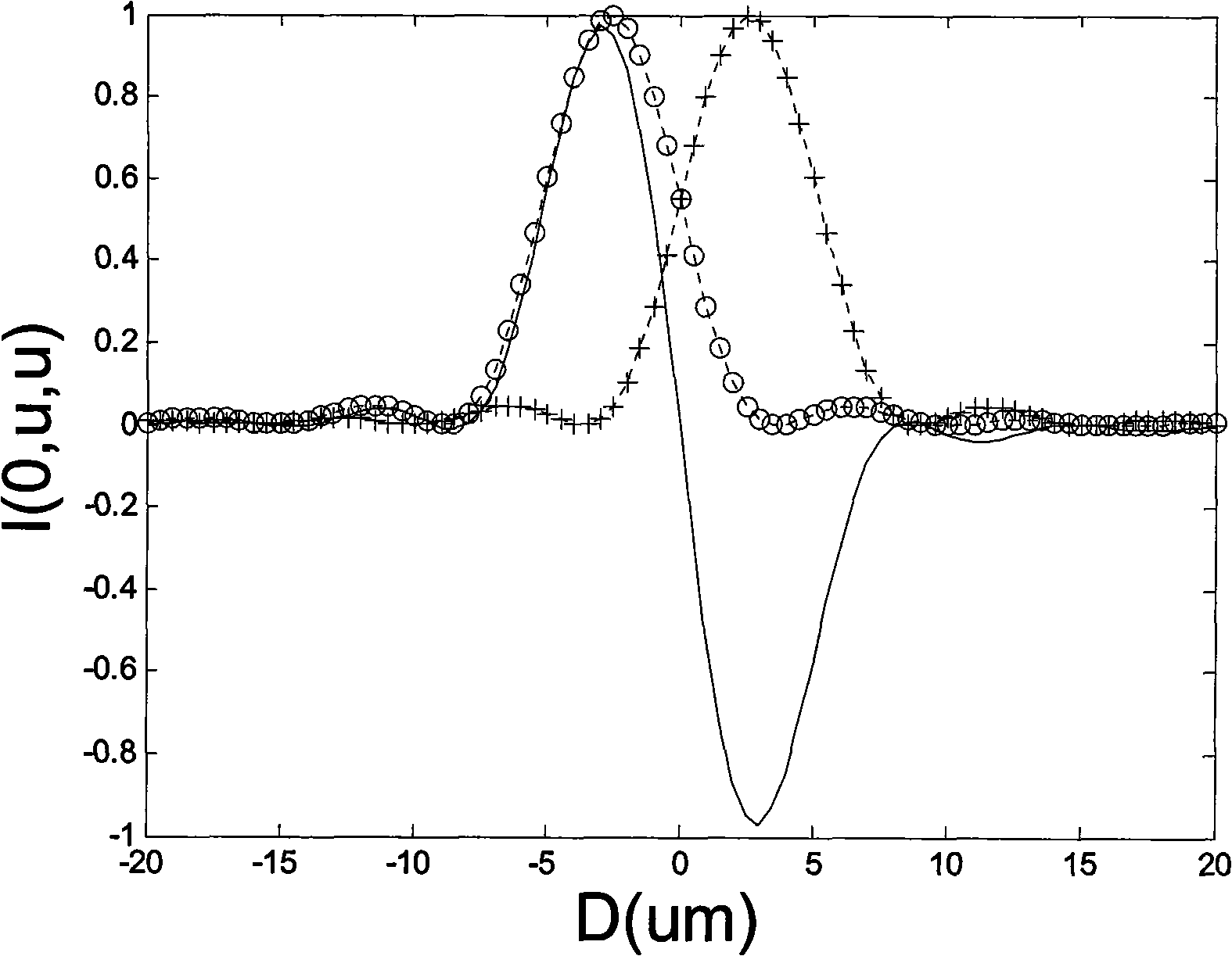
[0029] The technical principle of the present invention is: adopting the differential confocal microscopy imaging technology to arrange the confocal microscope receiving optical path into two detection optical paths before and after the focus, and the two intensity response signals with different phases detected by the two detectors are differentially The subtraction achieves the purpose of improving the axial resolution and improving the anti-interference ability. At the same time, the system includes a Raman spectrum analysis system, so that the system can simultaneously measure the material spectrum signal of the microscopic area of ​​the sample, and can analyze the material composition of the sample; , The introduction of diffractive light shaping devices to limit the measurement beam and compress the focal depth of the system to achieve the purpose of improving the r...


PUM


Abstract

The invention belongs to the technical fields of optical microscopy imaging and optical precision measurement and relates to a laser differential confocal spectrum microscopy tomography device which mainly comprises a Raman spectrum analysis part (25) and an objective lens (6), a polarizing spectroscope (7), a one-quarter glass slide (8) and a measurement objective lens (9) which are sequentially arranged along the optical path; the laser differential confocal spectrum microscopy tomography device further comprises a differential confocal detection part (26) which is positioned in the reverse direction of the reflection direction of the polarizing beam splitter. The differential confocal detection part is used for measuring the geometric position of a micro-area of a sample and focusing the sample to obtain image information of the micro-area of the sample; the Raman spectrum analysis part is used for analyzing the material spectrum of the detected area of the sample to obtain component information of the micro-area of the sample; the combination of the two parts can realize the nano-level micro-area spectrum measurement of the sample and simultaneously obtain the geometric feature and the material component information of the micro-area of the sample. The laser differential confocal spectrum microscopy tomography device provides a powerful observation means for bio-medicine, material science, high-energy physics and other forefront subjects.

Description

Technical field [0001] The invention belongs to the technical field of optical microscopic imaging and spectral measurement, and relates to a laser differential confocal map micro-tomography imaging device, which can be used for high-precision three-dimensional shape measurement of samples and spectral analysis of sample micro-zone material components. technical background [0002] In 1990, scholars such as G.J.Puppels first invented the confocal Raman spectroscopy technique when observing the morphology and composition of single cells and chromosomes and successfully used them in experiments. The principle of spectral imaging of the confocal Raman spectroscopy microscope is to place the point light source, the point measured object and the spectral point detector in the corresponding conjugate positions, which constitute the point illumination and point detection in optical imaging. Microscopic imaging system with analysis function. The basic structure of a typical confocal micr...

Claims


Application Information

Patent Timeline
IPC IPC(8): G01N21/65G01N21/64G01N13/00G02B27/09
Inventor 赵维谦王允邱丽荣
Owner BEIJING INSTITUTE OF TECHNOLOGYGY
Why Eureka
Try Eureka