Method for processing blind hole by laser

A laser processing and blind hole technology, applied in laser welding equipment, metal processing equipment, removing conductive materials by mechanical methods, etc., can solve the problem of small contact area between electroplated copper and copper layer at the bottom of the hole, decreased scanning speed, and the bottom of the blind hole. Increase the unevenness and other problems to achieve the effect of improving the quality and success rate of blind holes, eliminating the decrease in scanning speed, and eliminating the distortion of scanning trajectory

Inactive Publication Date: 2009-12-23
HUAZHONG UNIV OF SCI & TECH
View PDF0 Cites 75 Cited by
  • Summary
  • Abstract
  • Description
  • Claims
  • Application Information

AI Technical Summary

Problems solved by technology

[0006] (1) When the UV laser beam moves near the center of the circle, due to the small size of the moving track, whether the scanning galvanometer moves the UV laser beam or the working platform moves the workpiece, it will cause the UV laser beam scanning track to be distorted and the scanning speed to drop , resulting in inconsistency in the quality of blind hole processing
[0007] (2) Due to the decrease of the scanning speed of the UV laser beam in the vicinity of the center of the circle, the thermal effect accumulated in the area near the center of the circle will be larger than that of the surrounding area, resulting in the etching depth of the area near the center of the blin

Method used


Image

  • Method for processing blind hole by laser
  • Method for processing blind hole by laser
  • Method for processing blind hole by laser

Examples


example 1

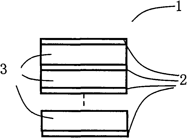
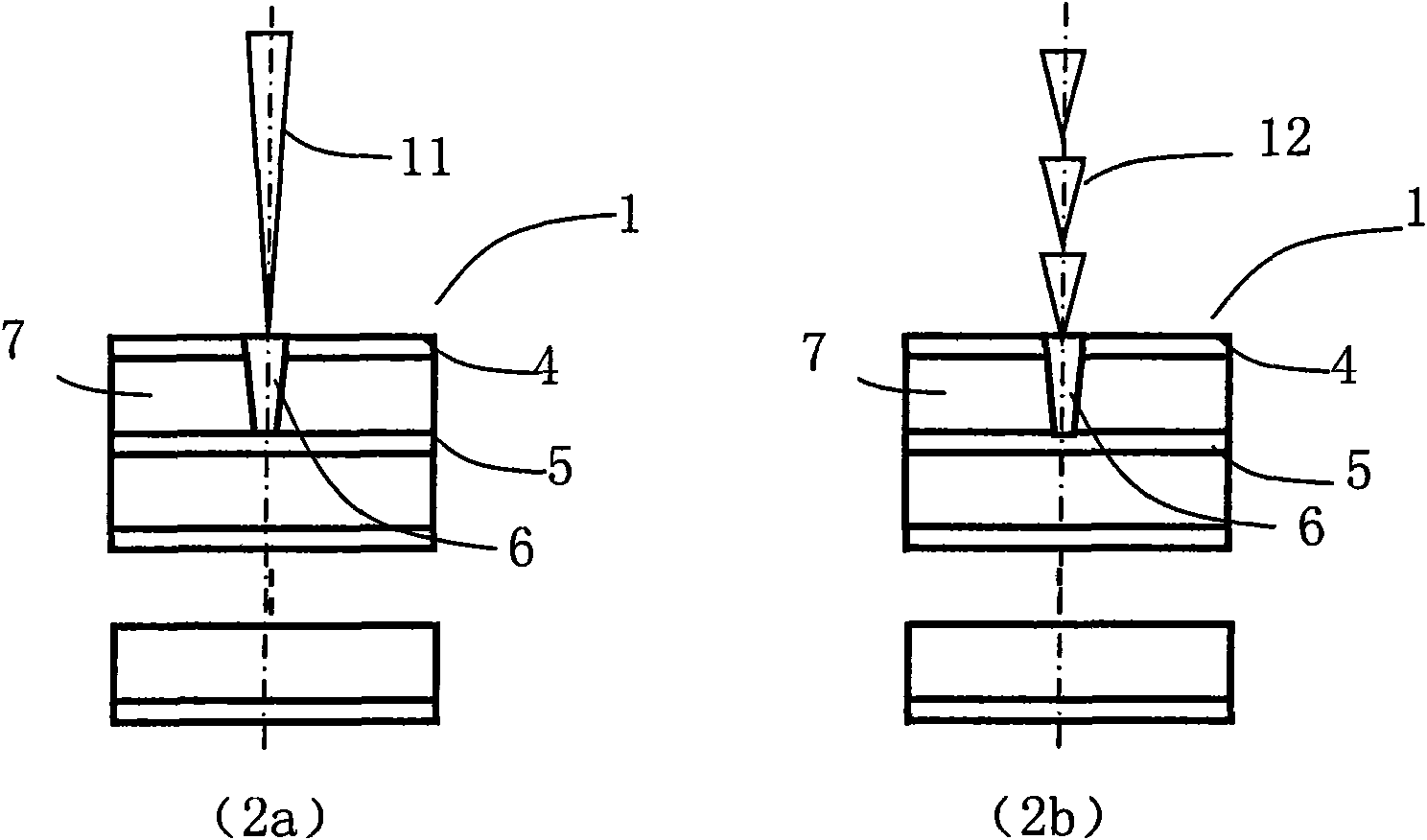
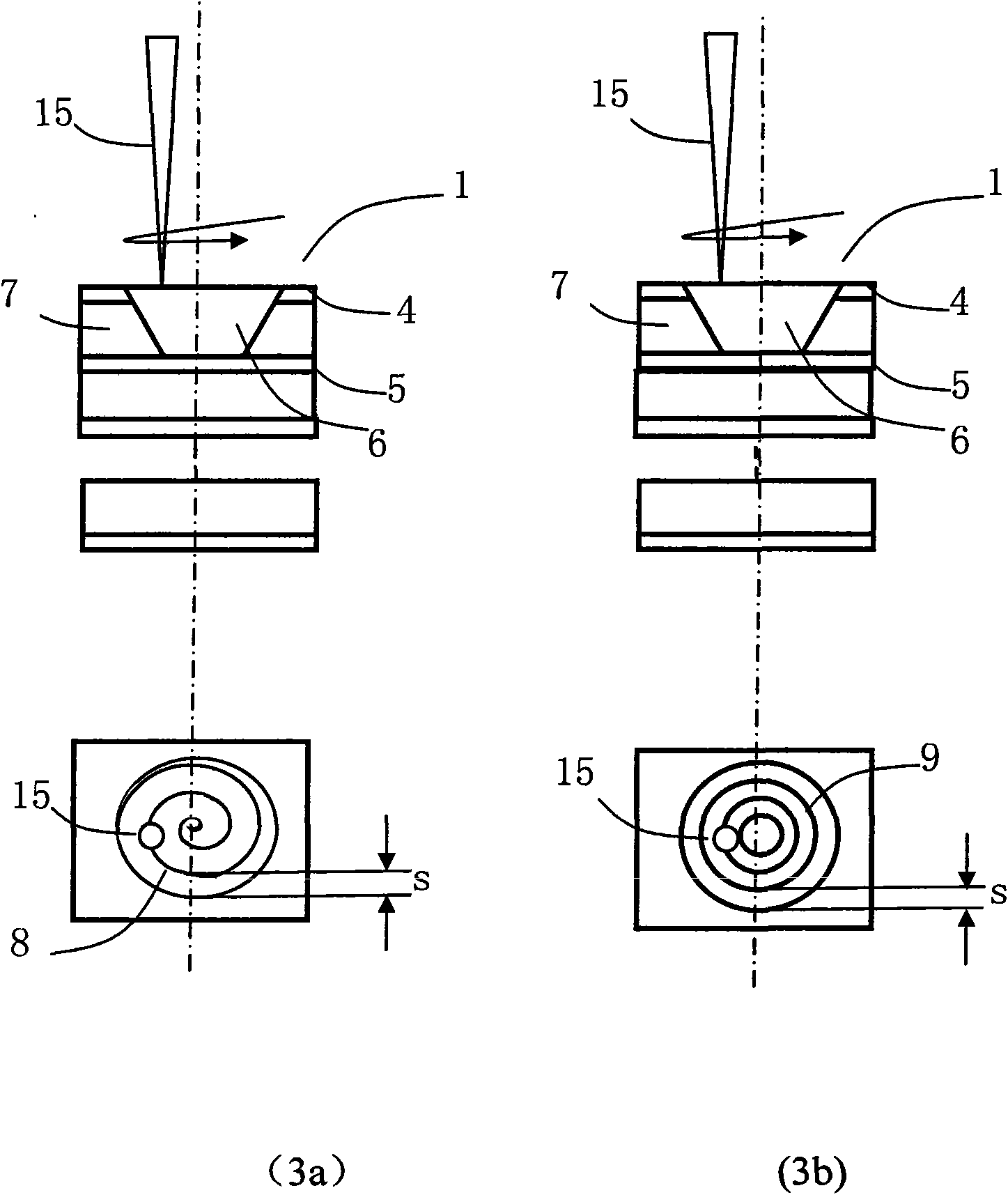
[0030] The present invention adopts the Awave-355-8W-25K model all-solid-state Q-switched ultraviolet laser produced by American Lightwave Company, the output wavelength is 355nm, the average power is from 0 to 10 watts, the frequency is set to 80kHz, and the structure is 4 layers of copper layers (thickness of 18 microns) and 3 layers of insulating material (thickness of 50 microns) composed of polyimide and epoxy resin adhesives (thickness of 50 microns) alternately laminated flexible circuit board (FCB) for drilling diameter of 200 microns The first-order blind hole machining. The processing parameters of the UV laser drilling blind holes are shown in Table 1. The verticality of the edge of the blind hole obtained by the invention is almost 90°, the copper recast layer is less than 0.89 micron, and the surface roughness of the copper layer at the bottom of the blind hole is 1.063 micron.

[0031] Table I

[0032]

[0033] second step

example 2

[0035] The present invention adopts the Awave-355-8W-25K model all-solid-state Q-switched ultraviolet laser produced by American Lightwave Company, the output wavelength is 355nm, the average power is from 0 to 10 watts, the frequency is set to 80kHz, and the structure is 4 layers of copper layers (thickness 35 microns) and 3 layers of insulating material (thickness 75 microns) composed of polyimide and epoxy resin adhesives (thickness 75 microns) alternately rolled flexible circuit board (FCB) for drilling diameter 100 microns The first-order blind hole machining. The processing parameters of the UV laser drilling blind holes are shown in Table 2. The verticality of the edge of the blind hole obtained by the invention is about 80°, the recasting layer of the copper layer is 0.95 micron, and the surface roughness of the copper layer at the bottom of the blind hole is 1.89 micron.

[0036] Table II

[0037]


PUM

PropertyMeasurementUnit
Surface roughnessaaaaaaaaaa

Abstract

The invention discloses a method for processing a blind hole by laser. The method combines fixed point UV laser impulse and UV laser spiral line or concentric circle scanning and is used for one-step blind hole processing or multi-step blind hole processing on multilayer circuit board. The method divides the UV laser blind hole drilling process into two parts, namely a part with an area near the circle center of the blind hole not more than UV laser spot diameter and a part with an area more than the UV laser spot diameter. Fixed point UV laser impulse is adopted to drill the blind hole, so as to remove material in the region with an area near the circle center not more than UV laser spot diameter; then UV laser spiral line or centric circle scanning method is adopted to move outside, so as to remove the material in the region with an area near the circle center more than UV laser spot diameter until meeting set blind hole size; and one-step blind hole or multi-step blind hole processing is drilled by UV laser through two steps or more steps. The method can ensure processing quality consistency of each blind hole, can greatly reduce bottom unevenness of the blind hole, and also can improve margin quality of blind hole processing.

Description

technical field [0001] The invention belongs to the technical field of laser processing applications, and in particular relates to a laser drilling method for blind holes. Background technique [0002] With the development of electronic products towards portability, miniaturization and diversification of functions, the size of printed circuit boards (PCBs) is getting smaller and smaller, thus putting forward higher and higher demands on the miniaturization of circuit boards. One of the keys to improving the miniaturization of circuit boards is the smaller and smaller micro-blind holes between different layers of circuits to meet the requirements of making high-density interconnection and ultra-high-density interconnection printed circuit boards. In order to effectively ensure the electrical connection between layers and the fixation of external devices, in high-speed and high-density PCB design, it is hoped that the smaller the blind hole, the better, so that not only can th...

Claims


Application Information

Patent Timeline
IPC IPC(8): H05K3/04H05K3/42B23K26/36B23K26/386
Inventor 段军李祥友王泽敏胡乾午曾晓雁
Owner HUAZHONG UNIV OF SCI & TECH
Why Eureka
Try Eureka