Method for preparing diesel component by catalytic cracking of coal tar light fraction

A catalytic cracking and catalytic cracking unit technology, which is applied in the field of catalytic cracking of light fractions of coal tar to prepare diesel components, can solve the problems of affecting the stability of diesel oil, the total yield of liquid products is not high, and the economic benefits are not obvious.

Active Publication Date: 2010-01-20
HANERGY TECH
View PDF2 Cites 12 Cited by
  • Summary
  • Abstract
  • Description
  • Claims
  • Application Information

AI Technical Summary

Problems solved by technology

[0006] Compared with the hydrogenation of petroleum secondary processing distillate oil, the key problems to be solved for the hydrogenation and upgrading catalyst of coal tar are: first, the oxygen content in coal tar is high, and the water produced in the reaction process will affect the activity of the hydrogenation catalyst, water Both thermal stability and strength have adverse effects; the second is that the high content of colloid and residual carbon in coal tar is easy to promote carbon deposition in the catalyst, which is easy to cause rapid deactivation of the catalyst; the third is that the sulfur and ni

Method used


Image

  • Method for preparing diesel component by catalytic cracking of coal tar light fraction
  • Method for preparing diesel component by catalytic cracking of coal tar light fraction

Examples


Example Embodiment

[0041] Example 1

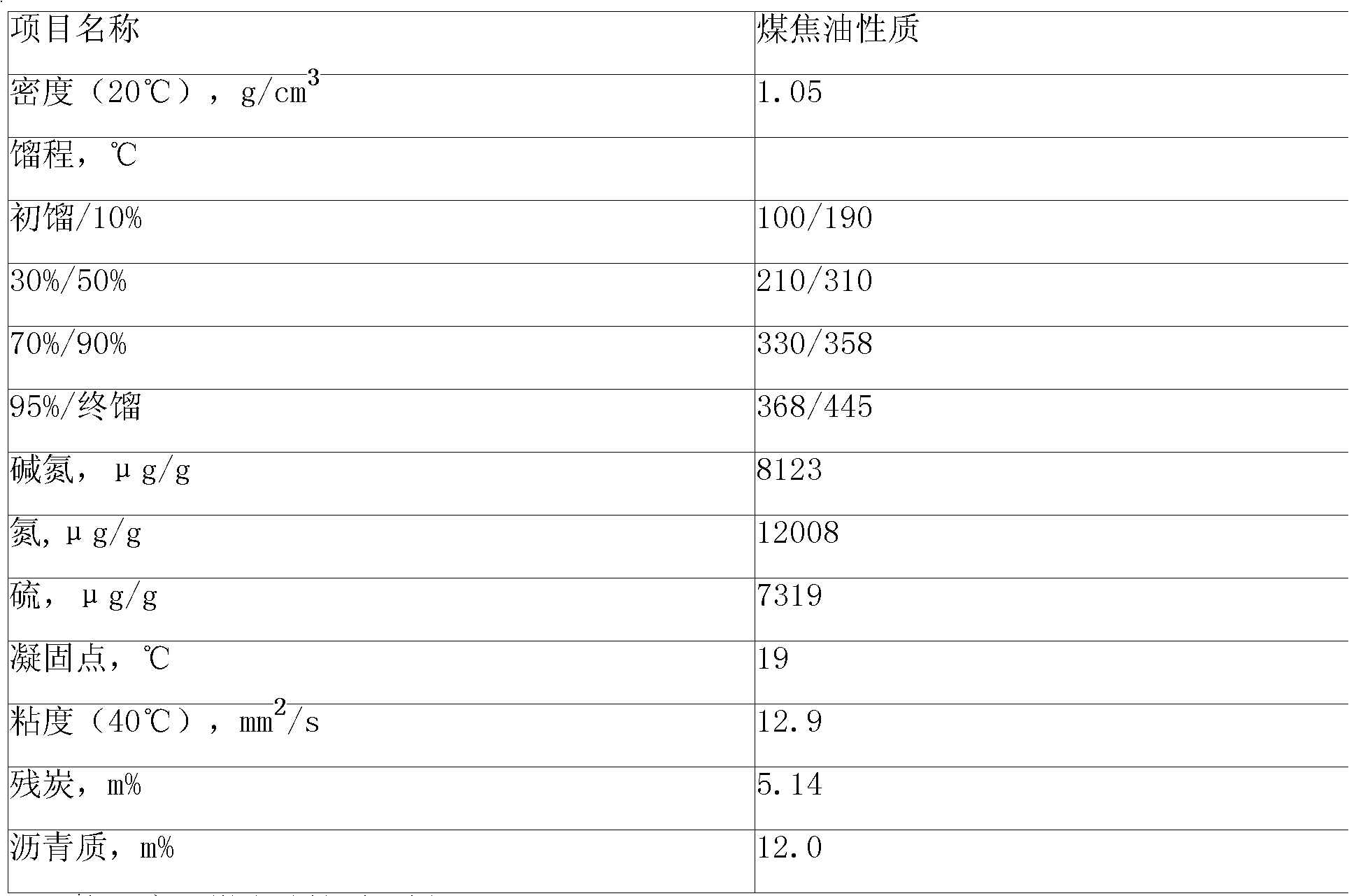
[0042] The coal tar used is medium temperature coal tar; the collected light fraction is 160-320°C fraction, 350g in total.

[0043] Put the light fraction of coal tar in an upflow fixed-bed reactor at a temperature of 420°C, a pressure of 0.15Mpa, and an oil-gas space velocity of 1h -1 Under the conditions of reaction, the diesel component is obtained, and its properties are shown in Table 4.

[0044] The catalyst used in the upflow fixed-bed reactor is a high-silicon Y-type molecular sieve catalyst loaded with La, with a pore volume of 0.25-0.30ml / g and a specific surface area of ​​150m 2 / g, the rare earth element La accounts for 2% of the weight of the catalyst.

[0045] Table 4 embodiment 1 gained diesel oil component property analysis data

[0046] project name

[0047] copper corrosion

Example Embodiment

[0048] Example 2

[0049] The coal tar used is medium temperature coal tar; the collected light fraction is 180-310°C fraction, 300g in total.

[0050] Put the light fraction of coal tar in an upflow fluidized bed reactor at a temperature of 400°C, a pressure of 0.3Mpa, and an oil-gas space velocity of 0.8h -1 Under the condition of reaction, diesel oil component can be obtained.

[0051] The catalyst used in the upflow fluidized bed reactor is a high silicon Y-type molecular sieve catalyst loaded with Ce, with a pore volume of 0.25-0.50ml / g and a specific surface area of ​​100m 2 / g, the rare earth element Ce accounts for 3% of the weight of the catalyst.

Example Embodiment

[0052] Example 3

[0053] The coal tar used is low-temperature coal tar; the collected light fraction is 180-310°C fraction, 290g in total.

[0054] Put the light fraction of coal tar in an upflow fixed-bed reactor at a temperature of 450°C, a pressure of 0.05Mpa, and an oil-gas space velocity of 2.5h -1 Under the condition of reaction, diesel oil component can be obtained.

[0055] The catalyst used in the upflow fixed-bed reactor is a high-silicon Y-type molecular sieve catalyst loaded with Nd, with a pore volume of 0.25-0.40ml / g and a specific surface area of ​​200m 2 / g, the rare earth element Nd accounts for 5% of the weight of the catalyst.


PUM

PropertyMeasurementUnit
Pore volumeaaaaaaaaaa
Specific surface areaaaaaaaaaaa
Pore volumeaaaaaaaaaa

Abstract

The invention discloses a method for preparing a diesel component by catalytic cracking of coal tar light fraction, which comprises the following step: placing a coal tar light fraction in a catalytic cracking device under conditions of a temperature of between 400 and 450 DEG C, a pressure of 0.05and 0.4MPa and an oil gas airspeed of 0.5 to 2.5 hour<-1> to obtain the diesel component. The method has the advantages of simple flow, high conversion rate and stable operation and belongs to the field of coal tar deep processing.

Description

technical field [0001] The invention relates to a method for deep processing of coal tar, in particular to a method for preparing diesel oil components by catalytic cracking of light fractions of coal tar. Background technique [0002] How to effectively utilize coal resources and make them meet the requirements of environmental protection, meet the allocation of other natural resources in coal producing areas, conform to the long-term development strategy of the region, and finally conform to the national industrial policy has always been the research direction of the state, local governments and enterprises. my country has a large amount of coal tar resources, how to effectively use coal tar is an important link in the comprehensive utilization of coal. Due to the shortage of petroleum resources, more and more companies are working hard to convert coal tar, an unclean resource, into a clean alternative fuel that can be used by diesel engines. [0003] The components in co...

Claims


Application Information

Patent Timeline
IPC IPC(8): C10G11/00C10G11/05
Inventor 肖钢侯晓峰闫涛
Owner HANERGY TECH
Why Eureka
Try Eureka