
Silver-coated material for movable contact component and method for manufacturing such silver-coated material

A technology of silver coating and moving contact, which is applied in the direction of contact manufacturing, contact parts, contact materials, etc., and can solve problems such as silver peeling and heating of the switch part

Inactive Publication Date: 2010-03-24
FURUKAWA ELECTRIC CO LTD
View PDF3 Cites 22 Cited by
  • Summary
  • Abstract
  • Description
  • Claims
  • Application Information

AI Technical Summary

Problems solved by technology

It is known that the switching part is heated due to repeated switching in a short period of time, and the oxygen permeating the silver plating layer oxidizes the nickel, and the silver is easily peeled off.

Method used


Image

  • Silver-coated material for movable contact component and method for manufacturing such silver-coated material
  • Silver-coated material for movable contact component and method for manufacturing such silver-coated material
  • Silver-coated material for movable contact component and method for manufacturing such silver-coated material

Examples


Embodiment 1~8

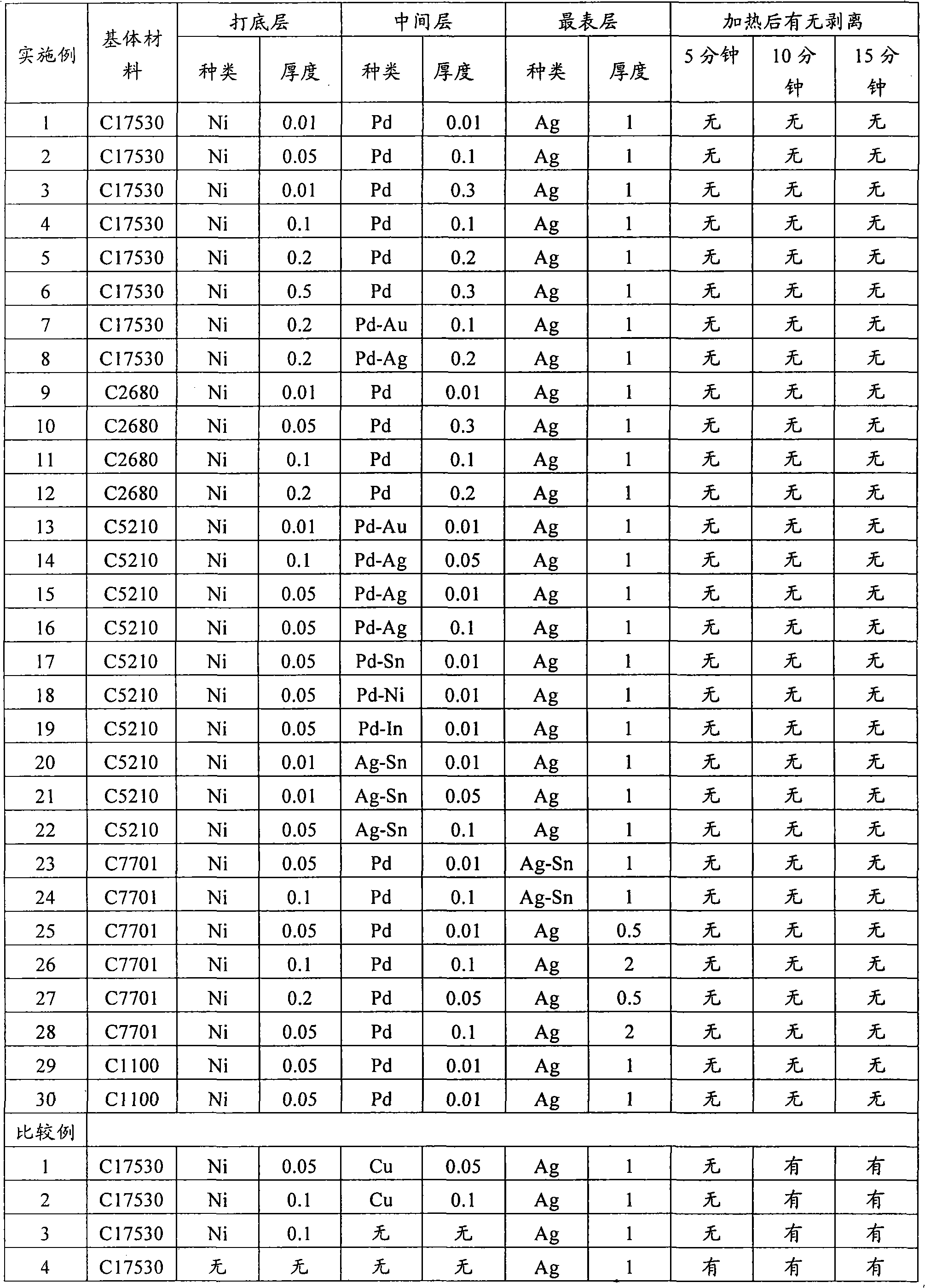
[0045] A plate material of beryllium copper (Be—Cu: C17530) having a thickness of 0.25 mm and a plate width of 100 mm was subjected to the following treatment to obtain a silver-coated material having a layer structure shown in Table 1.

[0046] (1) Pretreatment: immerse in a mixture of 4% sulfuric acid and 200g / l sodium dichromate for 1 to 3 minutes at room temperature, and then perform cathodic degreasing (50°C, 2A / dm 2 ).

[0047] (2) Nickel primer plating: use a plating solution containing 5g / l nickel chloride and 30% free hydrochloric acid, at a cathode current density of 2A / dm 2 Carry out under certain conditions to form a bottom layer.

[0048] (3) Activation treatment: The Cu-Be strips plated with the nickel primer layer are kept in warm to hot water at 40 to 90° C. for 3 seconds or more. The temperature of the Be-Cu strip from electrolytic degreasing to the activation treatment was controlled by immersing the Be-Cu strip in a water washing tank whose temperature was...

Embodiment 9~30

[0055] Brass (Cu-Zn: C2680), phosphor bronze (C5210: Cu-Sn-P), copper-nickel-zinc alloy (Cu-Ni-Zn: C7701), refined copper (pure copper) with a thickness of 0.25 mm and a plate width of 100 mm System: C1100) plate, degreasing (immersion in 60g / l NaOH solution for 30 seconds) and pickling (immersion in 10% sulfuric acid for 30 seconds), and then carry out (2) in Examples 1-8 ~(7) treatment, the silver-coated material with the layer structure shown in Table 1 was obtained. In addition, the difference from Examples 1 to 8 is that in addition to the above-mentioned (4) or (5) plating, the intermediate layer plating is also subjected to plating selected from the following (8) and (9). In addition, after the plating in (6) is performed on the outermost layer, plating corresponding to the type shown in (7) or the following (9) is also performed.

[0056] (8) Intermediate layer (Pd-Sn, Pd-Ni, Pd-In) plating: Plating using various metal salts containing 100g / l palladium sulfate, 30g / l ...


PUM

PropertyMeasurementUnit
thicknessaaaaaaaaaa
thicknessaaaaaaaaaa
thicknessaaaaaaaaaa

Abstract

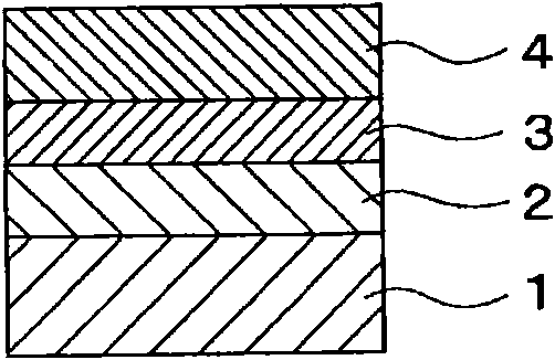
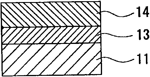
In a silver-coated material for a movable contact component, a conductive base material (1) composed of copper or a copper alloy is covered with a base layer (2), which is composed of nickel or a nickel alloy and has a thickness of 0.01-0.5¢mu!m, and the base layer (2) is covered with an intermediate layer (3), which is composed of palladium or a palladium alloy or a silver-tin alloy and has a thickness of 0.01-0.5¢mu!m, and on the intermediate layer (3), an outermost layer (4) composed of silver or a silver alloy is formed.

Description

technical field [0001] The present invention relates to a silver coating material for a movable contact part and its manufacturing method. Background technique [0002] In the past, push switches used in mobile phones and portable terminal devices used phosphor bronze or beryllium copper. A material obtained by performing silver plating on a permanent base material. [0003] In the past, a nickel primer layer was formed on a conductive base material, especially an iron-based alloy such as stainless steel, and then a silver surface layer was directly plated. On the other hand, due to the popularization of e-mail in mobile phones, the operation of repeated switching has increased. It is known that the switching part is heated due to repeated switching in a short time, and the oxygen permeating the silver plating layer oxidizes the nickel, thereby easily causing the silver to peel off. [0004] In order to prevent this phenomenon, it has been proposed to use, for example, a ...

Claims


Application Information

Patent Timeline
Patent Type & Authority Applications(China)
IPC IPC(8): H01H1/023C25D5/12C25D7/00H01H1/04H01R13/03H01R43/16
CPCH01H1/021C25D3/12C25D3/46C25D5/12B32B15/018H01H1/023H01R13/03C25D5/36C25D7/00H01H11/045
Inventor 山口优小林良聪
Owner FURUKAWA ELECTRIC CO LTD
Learn More