Ultrasound-assisted vacuum electron beam welding method of magnesium and magnesium alloy

A technology of vacuum electron beam and welding method, applied in the field of magnesium and magnesium alloys, can solve the problems of affecting the energy density distribution of electron beam welding heat source, unable to achieve one-time welding forming effect, reducing deep penetration ability, etc. Welding quality, effect of improving densification

Inactive Publication Date: 2010-04-14
CHONGQING UNIV OF TECH
View PDF0 Cites 4 Cited by
  • Summary
  • Abstract
  • Description
  • Claims
  • Application Information

AI Technical Summary

Problems solved by technology

However, the electron beam defocusing welding process affects the energy density distribution of the electron beam welding heat source, reduces its deep penetration ability, and obtains a shallower penetration depth of the weld. In some deep penetration welding occasions, the required once Welding Forming Effect

Method used


Image

  • Ultrasound-assisted vacuum electron beam welding method of magnesium and magnesium alloy
  • Ultrasound-assisted vacuum electron beam welding method of magnesium and magnesium alloy
  • Ultrasound-assisted vacuum electron beam welding method of magnesium and magnesium alloy

Examples


Embodiment 1

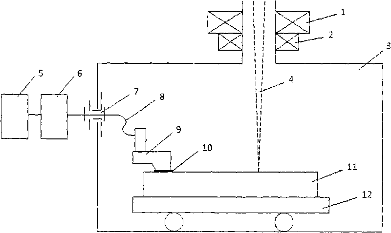
[0034] Embodiment 1: as figure 2 with image 3 As shown, the magnesium alloy weldment 11 to be welded is the butt joint of two flat plate structures with a thickness of 10 mm. Clamp the two pieces of weldment 11 on the workbench and transmission system 12 in the vacuum welding chamber 3 through the clamp, apply the coupling agent 10 on the pressing surface of the ultrasonic introduction device 9, and then put the ultrasonic introduction device 9 through the pressure of the spring The mechanism is pressed onto the surface of a weld bead of one of the workpieces to be welded. The signal wire 8 of the ultrasonic introduction device 9 is drawn out through the wire vacuum sealing structure 7 on the wall of the vacuum welding chamber, and is electrically connected with the ultrasonic vibration system inside and outside the vacuum welding chamber 3, and the stabilized power supply 5 provides power for the ultrasonic generator 6. Then close the vacuum welding chamber 3, pump the el...

Embodiment 2

[0035] Embodiment 2: as figure 2 with Figure 4 shown, with image 3 Compared with the process flow shown, Figure 4 The process flow adds the electron beam remelting process assisted by ultrasonic waves. The magnesium alloy weldment 11 is a fillet joint between a horizontal plate with a thickness of 10mm and a vertical plate with a thickness of 10mm. Clamp the two pieces of weldment on the workbench and the transmission system 12 through the fixture, apply the coupling agent 10 on the pressing surface of the ultrasonic introduction device 9, and then press the ultrasonic introduction device 9 to the workpiece to be welded by the spring pressure mechanism The weld bead surface on one side of the transverse plate. The signal wire 8 of the ultrasonic introduction device 9 is led out through the wire vacuum sealing structure 7 on the wall of the vacuum welding chamber, so that the ultrasonic vibration generator 6 inside and outside the vacuum welding chamber 3 is electricall...


PUM


Abstract

The invention discloses an ultrasound-assisted vacuum electron beam welding method which is applied to magnesium and magnesium alloy and can solve the technical difficulty that magnesium, magnesium alloy and especially cast magnesium alloy generate pores, cold shut and other cavity-type defects in the vacuum electron beam welding process. During the vacuum electron beam welding process, the technology applies structure load ultrasound energy with certain frequency and amplitude of vibration, wherein the frequency of ultrasound is 20-50kHz and the amplitude of vibration is 5-40mum. By conducting continuous oscillation on a molten pool generated by vacuum electron beam welding and the nearby area to a certain extent, the method can effectively eliminate the pores, cold shut and other cavity-type defects in the welding process and obtain high-quality welding joints.

Description

technical field [0001] The invention relates to an ultrasonic-assisted vacuum electron beam welding method for magnesium alloys, which is suitable for welding magnesium and magnesium alloys, especially casting magnesium alloys. Background technique [0002] Magnesium alloy is a candidate practical metal material with potential development prospects and excellent performance, and is known as "the green engineering material of the 21st century". Due to the unique advantages of magnesium alloys in light weight, specific strength, thermal conductivity, electrical conductivity, vibration damping ability, energy storage, machinability, recyclability and dimensional stability, the application of magnesium alloys tends to be extensive. , has extremely important application value and broad application prospects in the fields of aviation, aerospace, automobiles, home appliances, electronic communications, and national defense and military affairs. [0003] The methods applied to magn...

Claims


Application Information

Patent Timeline
Patent Type & Authority Applications(China)
IPC IPC(8): B23K15/06B06B1/06
Inventor 罗怡叶宏李春天许惠斌
Owner CHONGQING UNIV OF TECH
Why Eureka
Try Eureka