Comprehensive utilization method and system for coal

A subsystem and pulverized coal technology, applied in the comprehensive utilization method and system field of coal, can solve the problems of inability to reduce carbon dioxide and high cost

Active Publication Date: 2010-08-04
ENN SCI & TECH DEV
View PDF4 Cites 28 Cited by
  • Summary
  • Abstract
  • Description
  • Claims
  • Application Information

AI Technical Summary

Problems solved by technology

Although in view of the seriousness of the "greenhouse effect", European and American countries have begun to study coal-based near-zero-emission polygeneration systems in recent years, but due to the stable chemical properties of carbon dioxide, such coal-based near-zero-emissio

Method used


Image

  • Comprehensive utilization method and system for coal
  • Comprehensive utilization method and system for coal
  • Comprehensive utilization method and system for coal

Examples


Embodiment 1

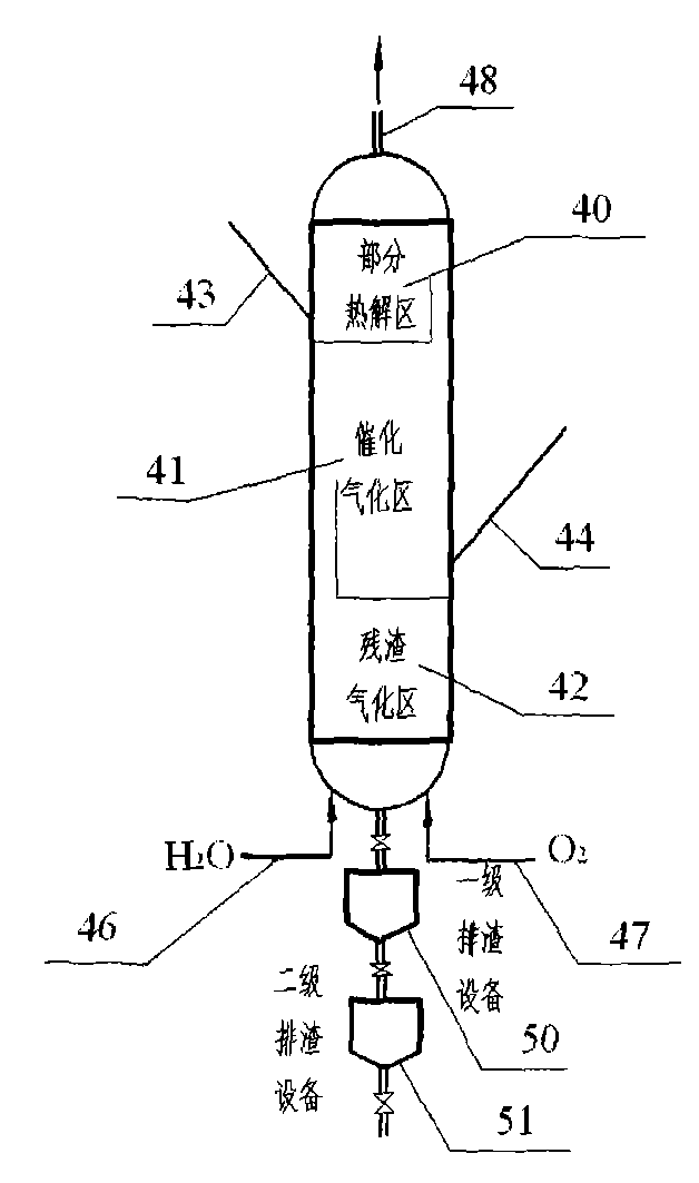
[0092] see figure 1 , figure 1The gasifier includes three zones from top to bottom, which are partial pyrolysis zone 40 , catalytic gasification zone 41 , and residue gasification zone 42 . The raw coal enters the partial pyrolysis zone 40 through the pipeline 43. The temperature of the partial pyrolysis zone 40 is 450-650°C. The gas stream from the catalytic gasification zone 41 heats the feed raw coal and pulverized coal in the partial pyrolysis zone 40 to make it generate Partial pyrolysis and hydropyrolysis to obtain methane-containing gas products, tar and pyrolyzed coal powder. The gaseous products and tars exit the gasifier in outlet line 48 to subsequent separation equipment. The pyrolyzed coal powder moves downward into the catalytic gasification zone 41 . Another part of coal and catalyst enters the catalytic gasification zone from the pipeline 44 in the form of mixture, and these coals, together with the pyrolyzed coal powder from the partial pyrolysis zone, are ...

Embodiment 2

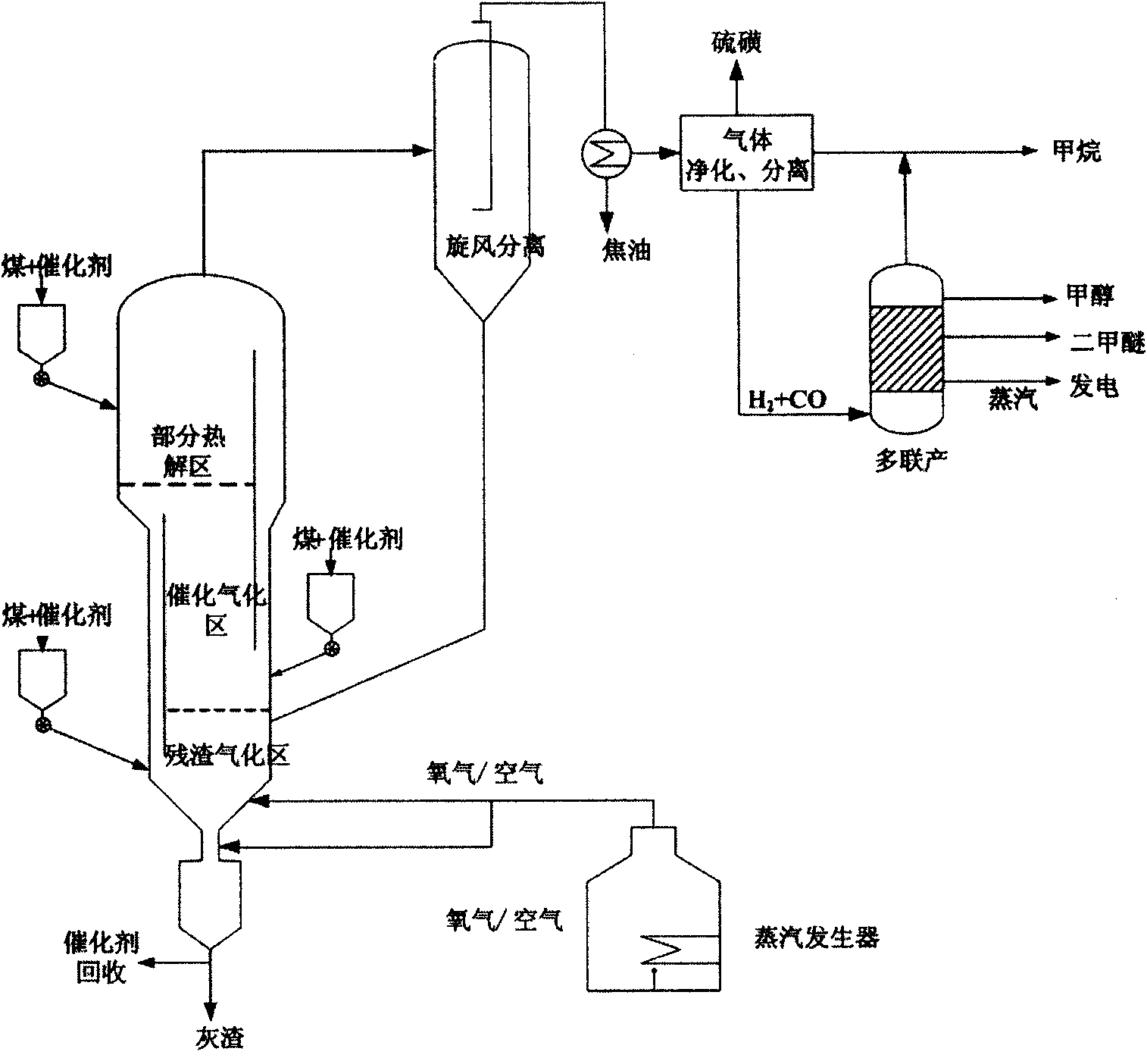
[0094] see Figure 4 , the outlet gas of the gasifier (mainly CH 4 , CO, H 2 and CO 2 , and a small amount of H 2 S and NH 3 etc.) through the isothermal dust filtration of the cyclone separator for gas-solid separation, the solid phase dust is returned to the gasifier for gasification reaction, and the gas phase is separated through the gas-liquid cooling separation unit for gas-liquid separation to obtain low-temperature tar. The crude synthesis gas is purified and separated to remove acid gases such as carbon dioxide and hydrogen sulfide to obtain methane. H separated from purification system 2 S is further processed to obtain sulfur. Remaining H 2 and CO into polygeneration sub-methods for the production of methane, methanol, dimethyl ether and the like. The steam produced by the polygeneration sub-process is used to generate electricity.

Embodiment 3

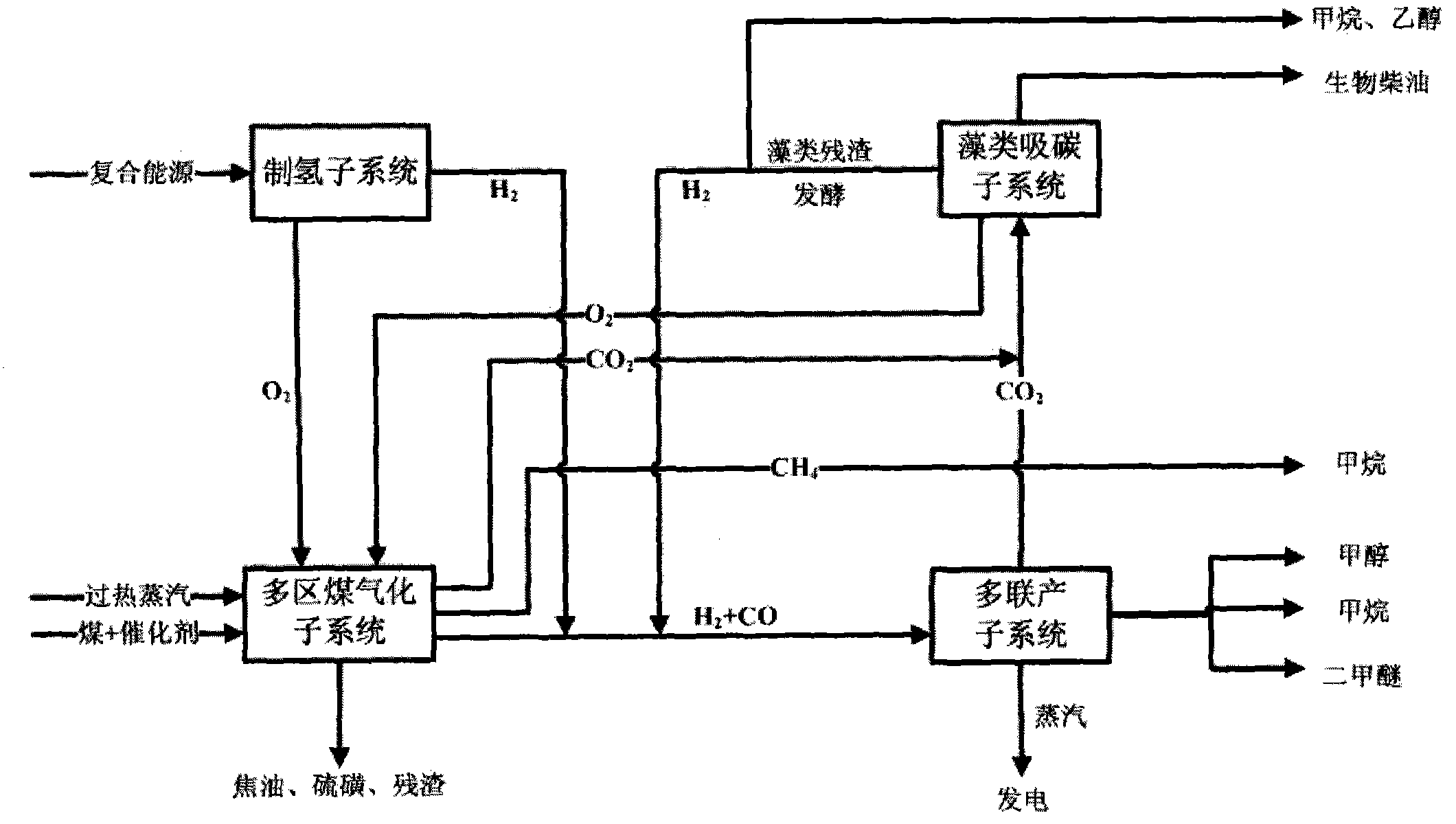
[0096] see figure 2 , the crude syngas produced by the multi-zone coal gasification sub-method is purified and separated from methane to produce syngas (mainly H 2 and CO) and the hydrogen of the hydrogen production method and the by-product hydrogen produced by the residue fermentation of the algae carbon absorption method are mixed, and sent to the multi-generation method, a part of which is directly methanated to produce methane, and the by-product water is returned to the multi-zone coal gasification method ; Another part of methanol is synthesized, a part of the produced methanol is used to produce dimethyl ether, and the other part can be sold directly. The carbon dioxide generated by the multi-zone coal gasification method and the polygeneration method is sent to the algae carbon absorption method to produce biodiesel, and at the same time, oxygen is co-produced. The algae residue is used for fermentation to produce one or more of the by-product hydrogen, methane or e...


PUM


Abstract

The invention provides a comprehensive utilization method for coal. The coal is transformed into methane and other clean energy chemical products and/or clean power by integrating a multi-region coal gasification sub-method, a coal-based poly-generation sub-method, a composite power source hydrogen production sub-method and/or an algae carbon absorption sub-method, and an ecological cycle mode for development and utilization of coal resources is formed, wherein in the multi-region coal gasification sub-method, methane-containing gas flow is produced in the presence of a catalyst and a gasification agent by putting coal powder into a gasification furnace comprising a partial pyrolysis region, a catalytic gasification region and a residue gasification region. The invention also provides a system for implementing the comprehensive utilization method for coal.

Description

technical field [0001] The invention relates to coal chemical industry, in particular to a coal comprehensive utilization method and system in which a multi-zone coal gasification sub-method and a sub-system are coupled with other sub-methods and sub-systems. Background technique [0002] my country is a country rich in coal, poor in oil and little in gas. With the rapid development of society and economy, the demand for natural gas in my country has risen sharply, and its proportion in the energy structure has increased rapidly. However, domestic natural gas is still in the early stages of exploration and development, imports are also in the initial stage, and the supply capacity is seriously lagging behind, resulting in increasingly prominent contradictions between natural gas supply and demand. The use of coal, which has relatively large resource advantages in my country, can not only promote the efficient and clean utilization of coal; but also use the existing natural g...

Claims


Application Information

Patent Timeline
IPC IPC(8): C10J3/66C07C9/04C07C1/04C07C31/04C07C31/20C07C29/151C07C43/04C07C41/01B01J20/22C10L1/00C01B13/02C01B3/02C07C31/08C07C403/24C12P21/02C12P7/64C12P3/00C12P5/02C12P7/06C12P23/00C07K14/405C25B1/04F01K27/02C12R1/89
CPCC07C31/20Y02E50/343C10L1/00C07C29/151C07C43/04C10J2300/0976C10J2300/093C12M21/00B01J20/22Y02E50/17C10J3/482C10J2300/1681C07C31/04C07C9/04C10J2300/1665C10J3/66C10J2300/1662C10J2300/0986C10J2300/1684C07C1/04C10J3/721Y02E60/366C07C41/01C10L3/08C10J2300/0959Y02E50/10Y02E50/30Y02E60/36Y02P20/129Y02P20/133Y02P20/52
Inventor 毕继诚李金来甘中学
Owner ENN SCI & TECH DEV
Why Eureka
Try Eureka