

Nano carbon fiber, fuel cell and forming method thereof
A nano-carbon fiber and nano-fiber technology, applied in fuel cells, solid electrolyte fuel cells, battery electrodes, etc., can solve the problems of multiple processing procedures and high carbonization temperature, achieve high conductivity and improve performance
- Summary
- Abstract
- Description
- Claims
- Application Information
AI Technical Summary
Problems solved by technology
Method used
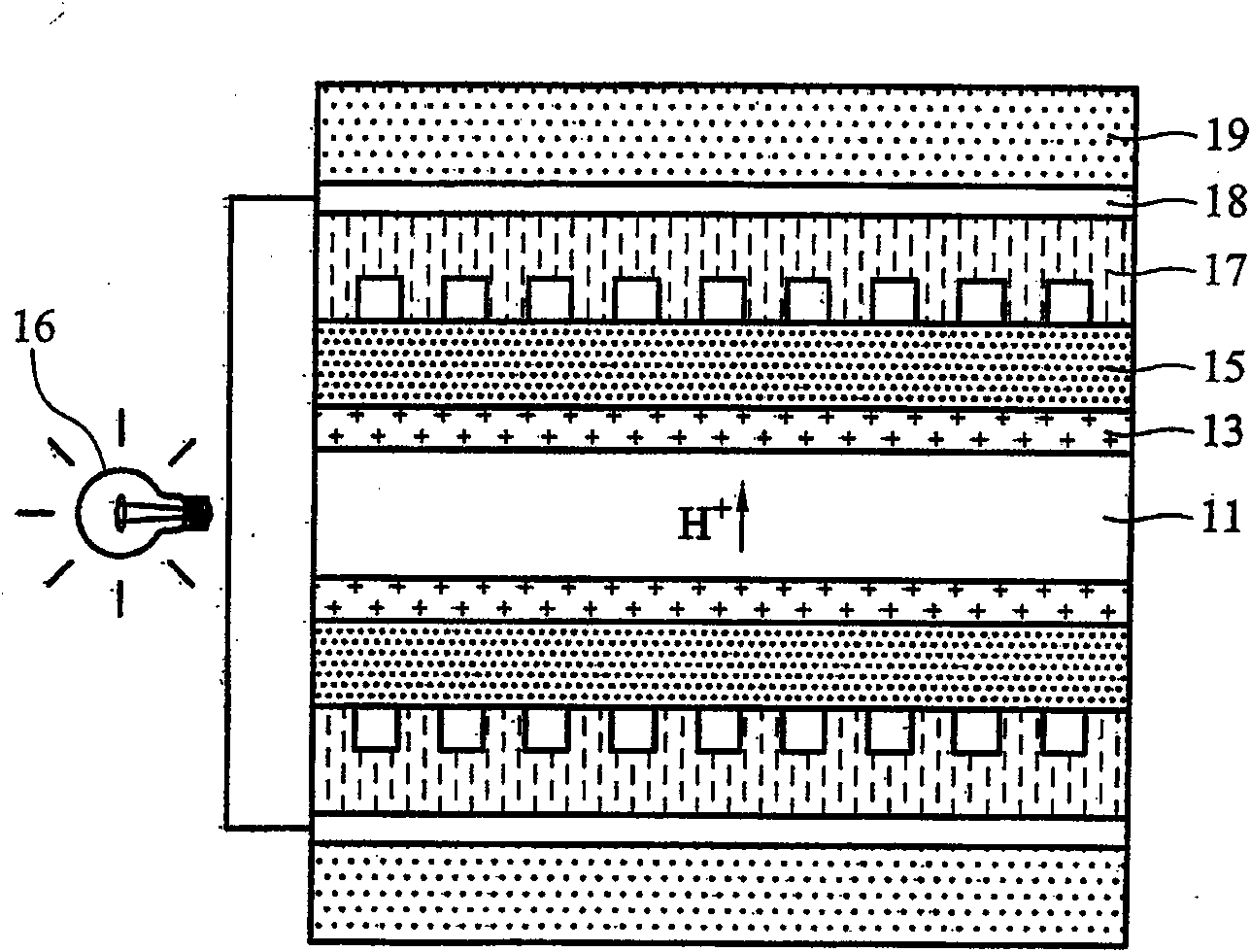
Image

Examples
Embodiment 1
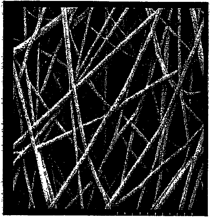
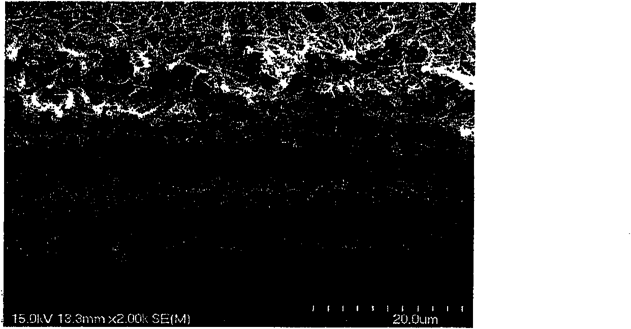
[0035] 13 g of polyacrylonitrile (purchased from Donghua Synthetic Fiber) was dissolved in 87 g of N,N-dimethylacetamide (hereinafter referred to as DMAc) to form a polyacrylonitrile polymer solution. The discharge spinning method is used for spinning, and the applied voltage is 39.5KV to form network-like nanofibers with diameters ranging from 200 to 700 nm. The above-mentioned nanofibers were placed in oxygen and heated at 270° C. for 180 minutes to obtain nano-oxygen fibers. Put the above-mentioned nano-oxygen fiber in nitrogen gas, carbonize the nano-oxygen fiber at 1000°C to make nano-carbon fiber, and its surface resistivity is 3.29Ω / cm 2 , the volume resistivity is 0.16Ω·cm.
Embodiment 2
[0037]Similar to Example 1, the difference is the temperature at which the nanofibers are oxidized. The nanofibers formed by spinning in Example 1 were placed in oxygen and heated at 280° C. for 180 minutes to obtain nanofibers. The conditions for subsequent carbonization of nano-oxygen fibers are the same, and the obtained carbon nano-fibers have a surface resistivity of 4.34Ω / cm 2 , the volume resistivity is 0.14Ω·cm.
Embodiment 3
[0039] Similar to Example 2, the difference lies in the method of carbonizing nano-oxygen fibers. With the microwave carbonization of 9kW the nano-oxygen fiber in embodiment 2, the nano-carbon fiber of gained, its surface resistivity is 1.42Ω / cm 2 , the volume resistivity is 0.29Ω·cm.
PUM
| Property | Measurement | Unit |
|---|---|---|
| diameter | aaaaa | aaaaa |
| diameter | aaaaa | aaaaa |
| Basis weight | aaaaa | aaaaa |
Abstract
Description
Claims
Application Information