
CO2 separation-liquefaction-purification system and method

A purification method and separation rate technology, which is applied in the field of CO2 separation-liquefaction-purification system, can solve the problems of unguaranteed separation and high energy consumption of separation, and achieve the effects of low cost, low recovery energy consumption and high safety

Inactive Publication Date: 2010-10-13
NORTH CHINA ELECTRIC POWER UNIV (BAODING)
View PDF8 Cites 14 Cited by
  • Summary
  • Abstract
  • Description
  • Claims
  • Application Information

AI Technical Summary

Problems solved by technology

CN101231130 discloses a CO that is expanded by separation in the mass transfer separation tower system 2 Purification method capable of separating CO with a purity higher than 97 mol % 2 Liquid, but extremely high purity CO is not guaranteed 2 Liquid, and its separation energy consumption is high

Method used


Image

  • CO2 separation-liquefaction-purification system and method
  • CO2 separation-liquefaction-purification system and method
  • CO2 separation-liquefaction-purification system and method

Examples


Embodiment 1

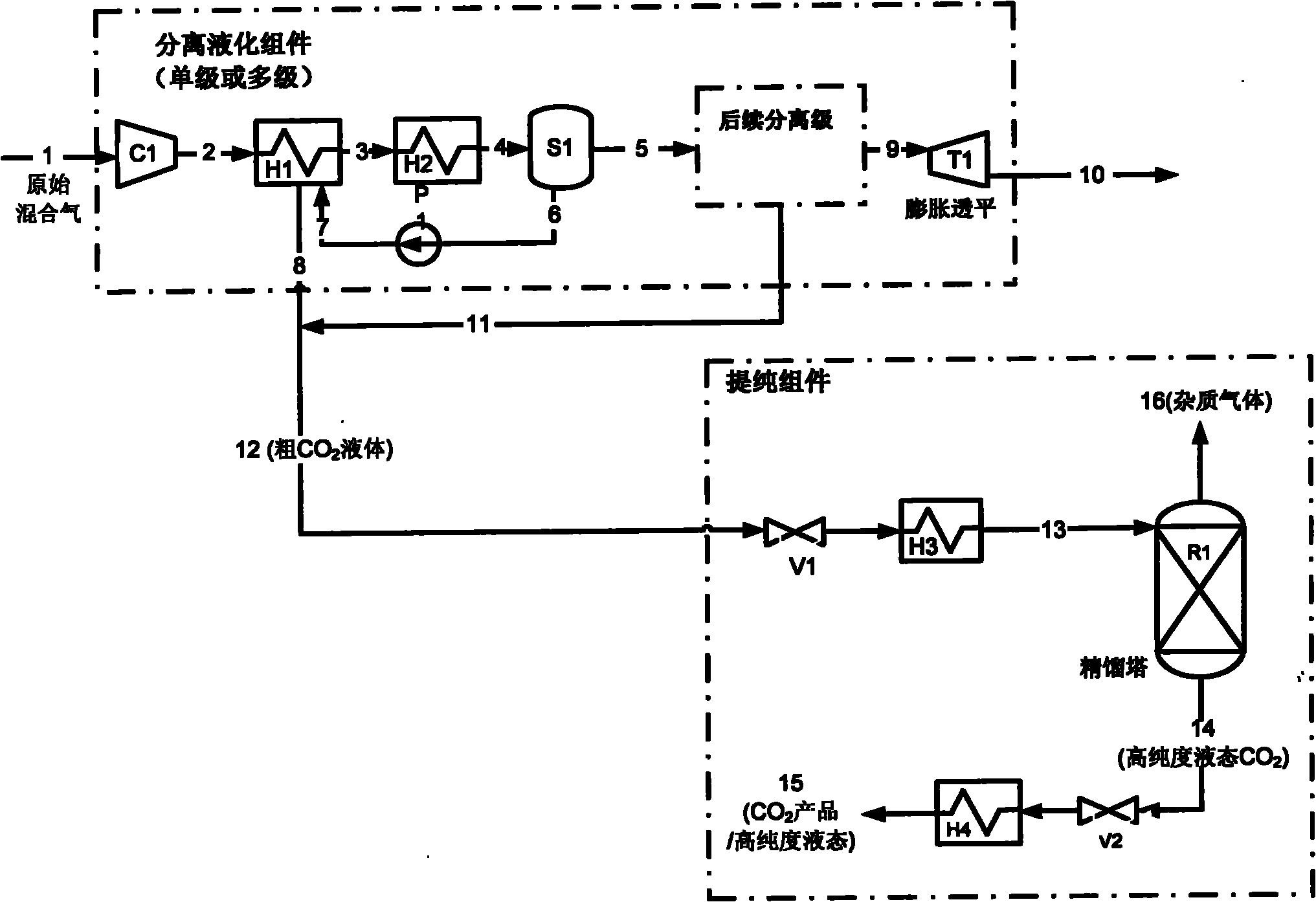
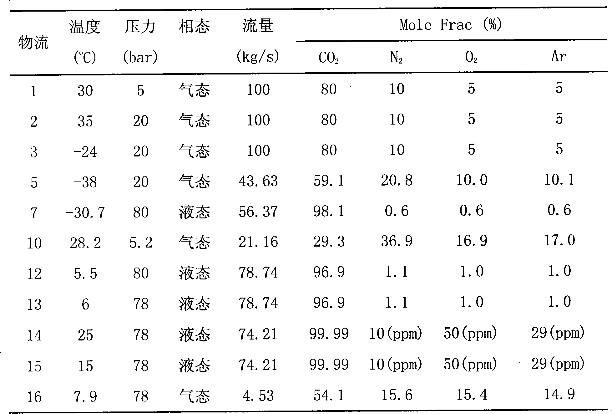
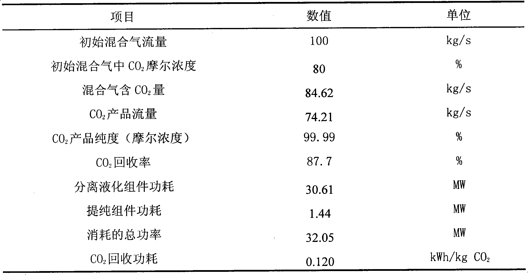
[0041] Select with CO 2 and N 2 , O 2 , Ar were 80%, 10%, 5%, 5% of the mixed gas as the research object, the analysis of CO 2 The characteristics of material flow and energy consumption when the separation-liquefaction-purification system separates it. The gas composition is similar to the flue gas composition of the combustion products under high-purity oxygen-enriched conditions using coal as fuel.

[0042]In the calculation, the compressor efficiency is taken as 0.8, the expansion turbine efficiency is 0.85, and the pump efficiency is 0.8. >5°C; minimum heat transfer temperature difference: general heat exchanger, pre-thermostat and post-set thermostat >8°C; low-temperature heat exchanger >2°C. The system is divided into two parts, the separation and liquefaction component and the purification component. The separation and liquefaction component adopts three-stage separation and liquefaction, that is, three sets of separation and liquefaction equipment are required.

...


PUM


Abstract

The invention discloses CO2 separation-liquefaction-purification system and method, belonging to the technical field of gas preparation. The system consists of a separation and liquefaction assembly and a purification assembly, and is used for separating various industrial mixing gases containing CO2, and separating, liquefying and purifying CO2 from mixed gases with higher CO2 concentration. The concrete technical scheme is that multi-level compression, repeated temperature reduction and multi-level separation modes are adopted in the separation and liquefaction assembly to enable the phase-transition temperature of CO2 to more approach room temperature and ensure higher separation rate and lower compression refrigeration energy consumption; and then, in the purification assembly, by the physical property difference of CO2 and various impurity components, the purification of liquid-state CO2 is realized through a rectification principle. The invention ensures that the CO2 recovery energy consumption is greatly reduced, the purified liquid-state CO2 product has high purity, which meets the requirements of general industrial application and transportation storage. In addition, the invention can be used for producing high-purity CO2 products with the molar concentration higher than 99.99 percent and has wide industrial market application prospect.

Description

technical field [0001] The invention belongs to the technical field of gas preparation, in particular to a CO 2 Separation-liquefaction-purification system and method. Background technique [0002] CO 2 Is a major greenhouse gas, due to the particularly large amount produced (the annual CO emission due to human activities 2 The amount is more than 20 billion tons), and its greenhouse effect contributes about 60% to global warming. Due to CO 2 About 90% of emissions come from the process of fossil energy utilization, so CO 2 The capture and storage of CO2 is considered as a way to reduce CO 2 Feasible technologies for emissions. [0003] Currently, CO 2 There are three main technical routes for capture: [0004] 1. CO after combustion 2 Separation and recovery refers to the separation and recovery of CO in the tail of the energy system, that is, the exhaust gas of the thermal cycle. 2 . Since CO can be recovered from exhaust gases of built energy systems 2 There i...

Claims


Application Information

Patent Timeline
IPC IPC(8): F25J3/02C01B31/20C01B32/50
CPCY02C10/12Y02C20/40Y02P20/10Y02P20/151
Inventor 徐钢杨勇平刘彤田龙虎段立强杨志平
Owner NORTH CHINA ELECTRIC POWER UNIV (BAODING)
Learn More