Receiving system in wireless optical communication and signal receiving method thereof

A wireless optical communication and receiving system technology, applied in the field of optical communication, can solve problems such as increased bandwidth, center wavelength drift of optical filters, signal fading, etc., to reduce processing technology requirements, increase or reduce array scale, and improve system The effect of integration

Inactive Publication Date: 2010-10-27
PEKING UNIV
View PDF3 Cites 22 Cited by
  • Summary
  • Abstract
  • Description
  • Claims
  • Application Information

AI Technical Summary

Problems solved by technology

Second, in order to increase the received signal power, a super-large focusing lens can be used to capture a large-diameter beam, but the processing technology of a large lens is very difficult, the processing cost is too high, and the volume and weight are large and the integration is low. Difficult to apply to spaceborne, shipborne and other occasions
At the same time, when receiving with a large aperture, after the light field on the receiving surface converges, the phase inconsistency of the light field at different positions on the receiving aperture may cause signal fading when combined on the photodetector
Third, the relevant research on spatial filter devices in traditional receiving schemes is still immature. Ordinary interference filters have a large bandwidth (usually dozens of nm, preferably 0.2-0.3nm), but they are only along the When the collimation axis enters the light field of the filter, if the inci

Method used


Image

  • Receiving system in wireless optical communication and signal receiving method thereof
  • Receiving system in wireless optical communication and signal receiving method thereof
  • Receiving system in wireless optical communication and signal receiving method thereof

Examples


Example Embodiment

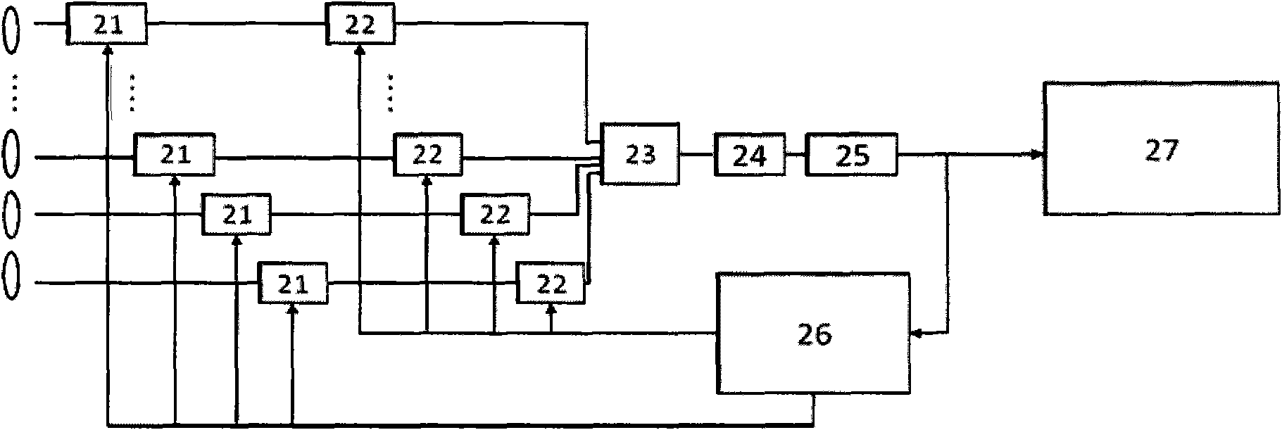
[0087] The wireless optical communication receiving system structure based on array receiving and coherent combination provides a highly sensitive and highly integrated receiving scheme for wireless optical communication. Its principle structure is as figure 2 Shown, including:

[0088] A focusing lens array that couples the spatial optical signal into the optical waveguide array or optical fiber array.

[0089] An optical waveguide array or optical fiber array serves as a transmission path for the received optical signal. The output end of the optical waveguide array or the optical fiber array is connected to a group of optical signal delayers 21. The optical signal delayer can be a commercial optical fiber adjustable true delayer, or a true delay module based on the slow light effect, which is used to adjust the signal delay of each optical signal so that the optical signal The telecom numbers are basically aligned. The output end of each optical signal delayer 21 is connecte...


PUM


Abstract

The invention relates to a receiving system in wireless optical communication and a signal receiving method thereof, and belongs to the field of optical communication. The system comprises a group of focusing lenses, a group of fiber or waveguide array, a group of optical signal delayers, a group of optical phase modulators, an optical coupler, an optical filter, a photoelectric detector, an analysis and calculation control module and a decoding and sampling judgment module. The method comprises the following steps of: 1) focusing and feeding spacial optical signals into a fiber array by adopting the group of focusing lenses; 2) performing phase delay and phase modulation on each path of the fiber array, and coupling-out a path of optical signals; 3) filtering the optical signals, converting the optical signals into electric signals, and outputting the electric signals to the decoding and sampling judgment module and the analysis and calculation control module respectively; and 4) in a communication time slot, restoring original information from the received electric signals by using the decoding and sampling judgment module, and in a reference time slot, performing feedback adjustment on each path of received optical signals by using the analysis and calculation control module. The receiving system and the signal receiving method thereof have the advantages of easy implementation and high precision.

Description

technical field [0001] The present invention relates to a long-distance wireless optical communication (Wireless Optical Communication, abbreviated as WOC) receiving system, in particular to a receiving system in wireless optical communication and a signal receiving method thereof, belonging to the field of optical communication. Background technique [0002] In recent years, with the rapid development of wireless communication, the number of wireless users has increased year by year, the services have become more diversified, and the data services have risen sharply, making the demand for broadband wireless signals and carrier frequencies to be extended to high frequencies increasingly urgent. Under such demands, wireless optical communication, as an extension of radio frequency wireless communication in the optical frequency domain, has received more and more attention, and has become one of the key technologies for ultra-broadband wireless communication in the future. Com...

Claims


Application Information

Patent Timeline
IPC IPC(8): H04B10/12H04B10/06G02B6/32G02B6/24H04B10/67
Inventor 杨筱舟方傲胡薇薇
Owner PEKING UNIV
Why Eureka
Try Eureka