Clutch facing

A technology of clutch face and working layer, which is applied in the field of automobile transmission system, can solve the problems of performance loss, not outstanding, and low cost, and achieve the effects of low cost, simple design, and easy manufacturing cost

Inactive Publication Date: 2010-11-03
十堰法雷诺动力科技有限公司
View PDF0 Cites 6 Cited by
  • Summary
  • Abstract
  • Description
  • Claims
  • Application Information

AI Technical Summary

Problems solved by technology

The clutch facings seen in the literature or in the market are all single-layer, that is, the entire product is composed of a single friction working layer. Performance requirements in terms of performance, good processability and low cost are required at the same time, which poses a great challenge to the formula design of the clutch face
The clutch facings that are applied often have gains and losses in various performances during formula design, in order to obtain a balance between various performance indicators, cost, and processability. The result is that all indicators are in an acceptable range. level, but not prominent enough

Method used


Image

  • Clutch facing
  • Clutch facing
  • Clutch facing

Examples


Embodiment 1

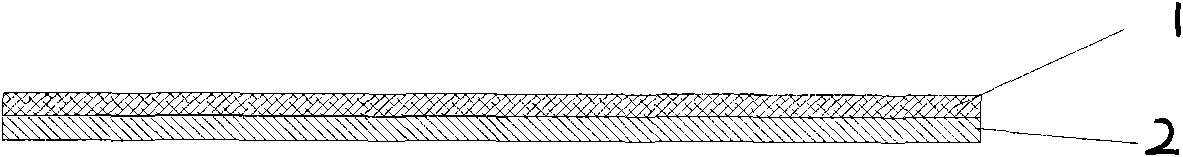
[0028] Implementation example 1 (two layers):

[0029] Friction working layer: the percentage by weight is 17% phenolic resin, 3% nitrile rubber, 10% chalcopyrite powder, 14% magnetite powder, 7% vermiculite powder, 3% aluminum oxide, 7% % wollastonite, 13% graphite, 6% light calcium carbonate, 1% antimony sulfide, 1% carbon black, and 18% barium sulfate are mixed evenly to make a slurry, and then the core-spun yarn Impregnation is carried out, and the impregnated core-spun yarn is dried and wound to form a friction working layer.

[0030] Structural layer: Mix 15% phenolic resin, 8% nitrile rubber, 28% wollastonite, 14% vermiculite powder, and 35% barium sulfate by weight to prepare a slurry, and then make a continuous glass The fibers are impregnated. The impregnated continuous glass fiber is dried and wound to form a support layer.

[0031]In the mold, the friction working layer is laid on the working surface, and the structural layer is laid on the back of the working s...

Embodiment 2

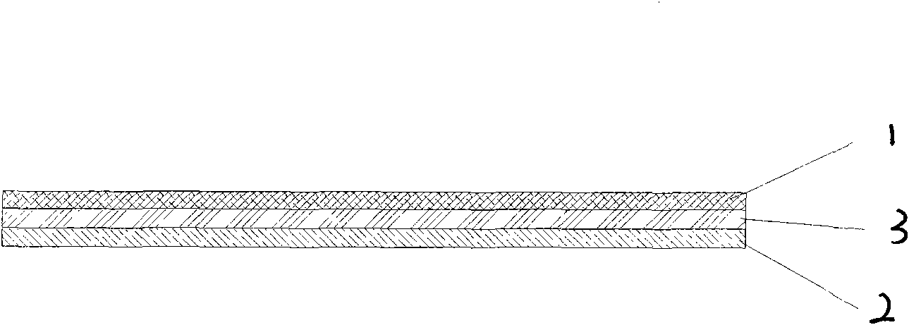
[0034] Implementation example 2 (three layers):

[0035] Friction working layer: the percentage by weight is 17% phenolic resin, 3% nitrile rubber, 10% chalcopyrite powder, 14% magnetite powder, 7% vermiculite powder, 3% aluminum oxide, 7% % wollastonite, 13% graphite, 6% light calcium carbonate, 1% antimony sulfide, 1% carbon black, and 18% barium sulfate are mixed evenly and prepared into a slurry, and then the core-spun yarn Impregnation is carried out, and the impregnated core-spun yarn is dried and wound to form a friction working layer;

[0036] Heat transfer layer: mix 50% steel fiber by weight, 15% phenolic resin, and 35% barium sulfate evenly to make heat transfer layer powder for later use;

[0037] Supporting layer: Mix 15% phenolic resin, 8% nitrile rubber, 28% wollastonite, 14% vermiculite powder, and 35% barium sulfate by weight to prepare a slurry, and then apply continuous glass The fiber is impregnated, and the impregnated continuous glass fiber is dried and...


PUM


Abstract

The invention discloses a clutch facing, which consists of a frictional working layer and a structural layer, wherein the frictional working layer is a working face; the back of the frictional working layer is provided with the structural layer; the number of the structural layer can be one or more, and the structural layers can be divided into a heat transfer layer and a support layer according to the action, wherein the heat transfer layer can be used as required; the frictional working layer participates in the friction operation and provides friction and abrasion properties required during using; the structural layer does not participate in the friction operation and provides other auxiliary properties for a clutch facing product; and the whole clutch facing product consists of two or more layers according to the property requirement. The frictional working layer and the structural layer are combined and thermally pressed to form the clutch facing so as to improve the comprehensive performance thereof and reduce the comprehensive cost.

Description

technical field [0001] The invention relates to an automobile transmission system, in particular to a clutch face. Background technique [0002] In the transmission system, the clutch is one of the key parts, and the clutch face is a product of composite friction material, and its main function is to realize power transmission through friction. [0003] With the rapid development of my country's industry, the heavy equipment manufacturing industry has achieved unprecedented success, and the export market has gradually expanded. This requires higher and higher performance requirements for high-load mechanical power coupling system clutches, such as trucks, engineering vehicles, and large buses. , large tonnage machine tools and equipment, etc. Most of these heavy equipment have the characteristics of large tonnage, high speed and frequent coupling. In order to meet these requirements, higher performance requirements are put forward for the clutch face, the most important key ...

Claims


Application Information

Patent Timeline
Patent Type & Authority Applications(China)
IPC IPC(8): F16D13/64D06M15/41D06M15/31D06M11/51D06M11/49D06M11/79D06M11/74D06M11/76D06M11/56C08L61/06C08K7/04C08K3/30C04B26/10
Inventor 张苏焦龙丁桢
Owner 十堰法雷诺动力科技有限公司
Why Eureka
Try Eureka