System and method for testing magnetoelectricity property of multiferroic thin-film material

A thin-film material and testing system technology, applied in the direction of magnetic performance measurement, etc., can solve the problem of unavoidable, inability to accurately measure the response signal, weak signal, etc., and achieve the effect of eliminating the influence of induced electromotive force

Inactive Publication Date: 2010-11-03
TSINGHUA UNIV
View PDF0 Cites 34 Cited by
  • Summary
  • Abstract
  • Description
  • Claims
  • Application Information

AI Technical Summary

Problems solved by technology

[0004] The shortcomings of the current testing technology are: the current testing system is all for bulk materials, because the response signal value of the thin film material is far smaller than that of the bulk material (at least three orders of magnitude smaller), it is impossible to accurately measure the response signal; due to the weak signal of the thin film material , the electromagnetic induction interference is strong, and the influence of electromagnetic interference on the test cannot be ruled out; due to the small and thin electrodes on the upper surface of the film material film, the current general-purpose lead test process will have a destructive effect on the sample, and the sample cannot be non-destructively detected; due to different types The magnetoelectric coupling mechanism of the multiferroic thin film materials is different, so it is impossible to select the test method for the test in a targeted manner

Method used


Image

  • System and method for testing magnetoelectricity property of multiferroic thin-film material
  • System and method for testing magnetoelectricity property of multiferroic thin-film material
  • System and method for testing magnetoelectricity property of multiferroic thin-film material

Examples


example 1

[0087] a) Example 1: Lead zirconate titanate (PZT)-cobalt ferrite (CFO) laminated multiferroic composite film

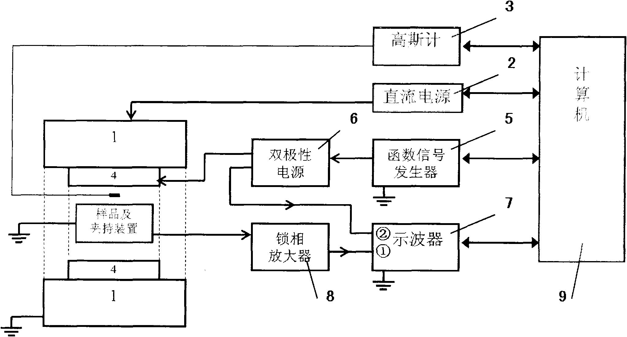
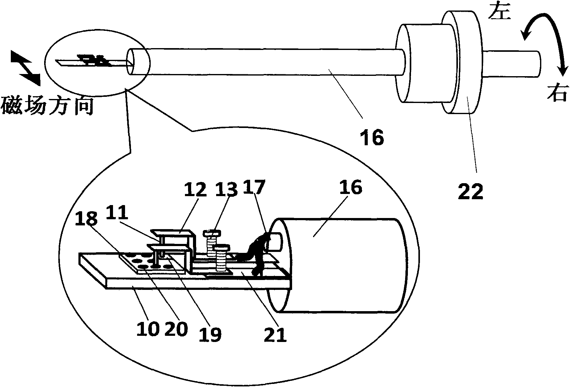
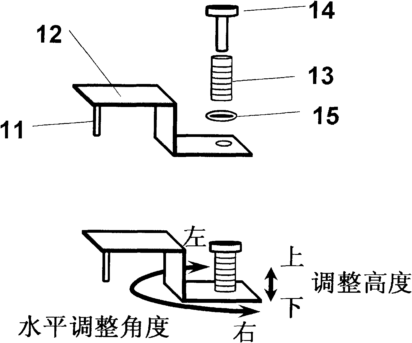
[0088] The lead zirconate titanate (PZT)-cobalt ferrite (CFO) laminated multiferroic composite film was prepared on the platinum-coated silicon substrate by the sol-gel method, and the electrode on the surface of the platinum-coated film was prepared. Hold it on the sample stage and fix it on the sample rod to ensure good contact, set H DC , f, make the alternating magnetic field generate a square wave waveform, then turn the turntable to gently rotate the sample rod within the range of ±5°, wait for the peak part in the response signal waveform to be eliminated, fix the angle, and change the DC bias magnetic field value in turn, through The computer reads the magnitude of the magnetoelectric signal under each bias magnetic field sequentially from the lock-in amplifier, and obtains the change law between the amplitude of the magnetoelectric coefficient and the DC bia...

example 2

[0089] b) Example 2: Barium titanate (BTO)-nickel ferrite (NFO) laminated multiferroic composite film

[0090] The barium titanate (BTO)-nickel ferrite (NFO) laminated multiferroic composite film was prepared on the niobium-doped strontium titanate single crystal substrate by pulsed laser deposition, and the electrode on the upper surface of the film was plated with platinum, and the sample to be tested was Clamp the probe on the sample stage and fix it on the sample rod to ensure good contact, set H DC 、H DC , so that the alternating magnetic field produces a sinusoidal waveform, and then turn the turntable to gently rotate the sample rod within the range of ±5°. When the phase difference between the response signal waveform and the reference signal is 0 or π, fix the angle, and change the frequency of the driving magnetic field in turn, through The computer reads the magnitude of the magnetoelectric signal under each bias magnetic field sequentially from the lock-in amplifi...

example 3

[0091] c) Example 3: Bismuth ferrite (BFO) single-phase multiferroic thin film

[0092] Using the sol-gel comparison method to prepare a bismuth ferrite single-phase multiferroic film on a platinum-plated silicon substrate, and plate an electrode on the surface of the platinum film, clamp the sample to be tested on the sample stage with a probe and fix it on the sample rod to ensure Good contact, set f, H DC =0Oe, make the alternating magnetic field generate a sine wave, then turn the turntable to rotate the sample rod slightly within the range of ±5°, when the phase difference between the response signal waveform and the reference signal is 0 or π, fix the angle, and change the driving magnetic field in turn Amplitude, the magnitude of the magnetoelectric signal under the alternating magnetic field of each different size is sequentially read from the lock-in amplifier by the computer, and the relationship between the electric polarization and the frequency of the alternating ...


PUM


Abstract

The invention relates to a system and a method for testing magnetoelectricity property of a multiferroic thin-film material, belonging to the field of property tests of materials. The system is characterized by comprising a DC bias magnetic field generating device, an AC magnetic field generating device, a thin-film sample probe holding device and a micro signal acquiring and amplifying device. The invention also provides a method for testing magnetoelectricity property of the multiferroic thin-film material. The invention can recognize the difference of an electromagnetic inductive interference signal and a multiferroic magnetoelectricity responding signal by accurately testing a thin-film micro electric responding signal so as to obtain a real amplitude of a magnetoelectricity coefficient of the multiferroic thin-film material under different frequencies and bias magnetic fields and also obtain the change law of thin-film sample polarization with an alternating magnetic field.

Description

technical field [0001] The invention relates to an instrument and a testing method for measuring the magnetoelectric properties of multiferroic thin film materials, belonging to the field of material performance testing. Background technique [0002] Multiferroic thin film materials have multiple ferroelectricity, ferromagnetism and other ferroelectricity at the same time, and have the coupling response of magnetism and electricity. It is a material system compatible with microelectronics technology and has broad application prospects. In multiferroic thin film materials, the magnetoelectric effect is one of the most important physical effects. The magnetoelectric properties can be measured and expressed by the magnetoelectric voltage coefficient or magnetoelectric polarization, and its variation with frequency and magnetic field is It is an important analytical tool to understand the magnetoelectric coupling mechanism and efficiency of multiferroic materials. Multiferroic ...

Claims


Application Information

Patent Timeline
Patent Type & Authority Applications(China)
IPC IPC(8): G01R33/12
Inventor 李峥南策文马静林元华
Owner TSINGHUA UNIV
Why Eureka
Try Eureka