

Ion plating device
A technology of ion coating and ion source, which is applied in the field of ion coating devices, can solve the problems of poor coating uniformity and short service life of ion sources, etc., and achieve uniform coating, good compactness, and enhanced film strength.
- Summary
- Abstract
- Description
- Claims
- Application Information
AI Technical Summary
Problems solved by technology
Method used
Image


Examples
Embodiment 1
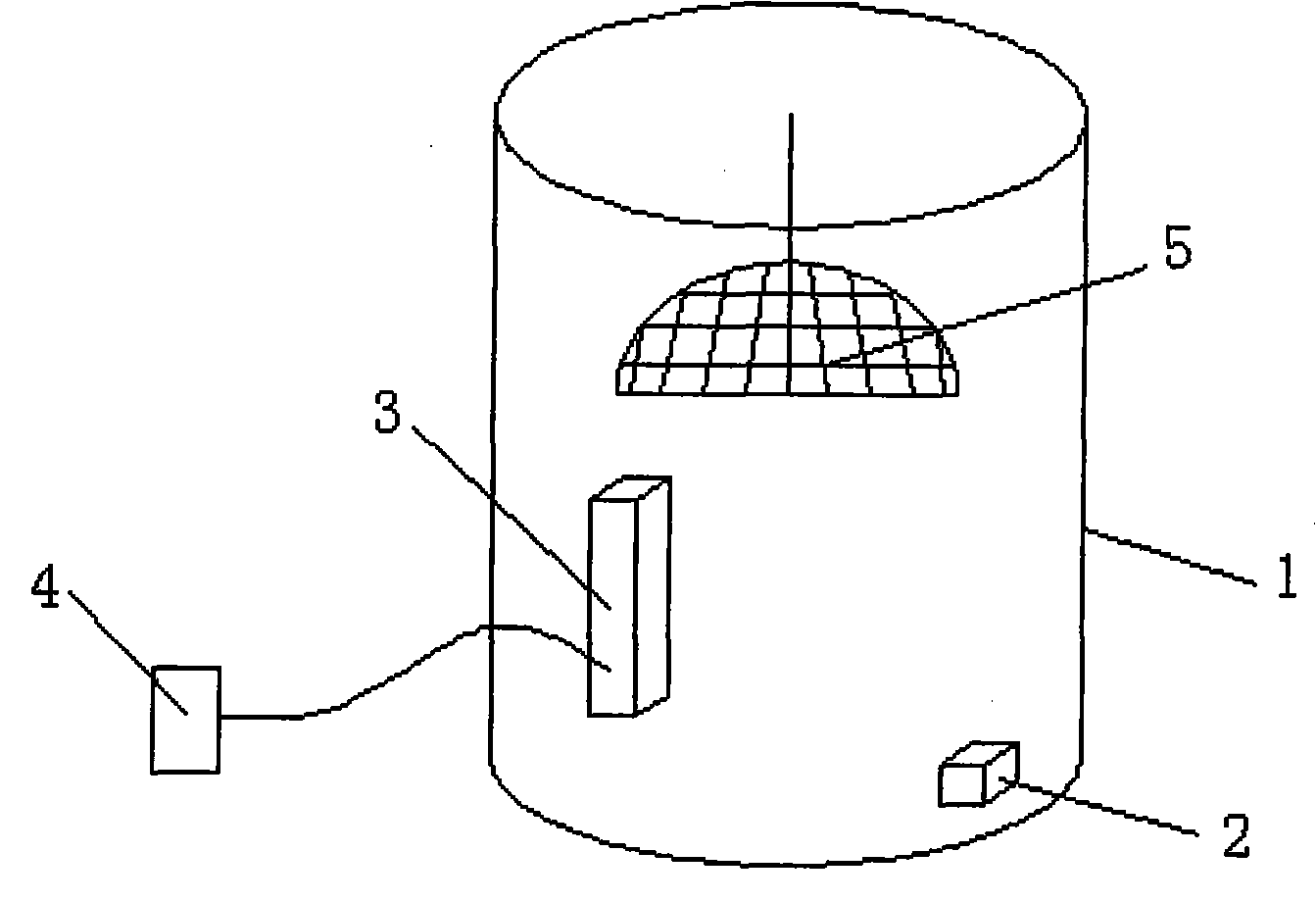
[0018] Such as figure 1 As shown, in the ion coating device of the present invention, the preferred scheme is that the coating furnace 1 is a cylinder, and the coating furnace is provided with an ion source 3 and a film material 2, and the ion source 3 and the ion source power supply arranged outside the coating furnace 1 4 are connected, ion source power supply 4 anode voltage 200-380V, anode current 8-20A, what pass into the coating furnace 1 is the mixed gas of oxygen and argon gas with a volume ratio of 1:2, and the gas flow rate is 30sccm (standard ml / minutes), the ion source 3 can coat 42-68 layers of film, and the top in the coating furnace 1 is provided with a coating umbrella 5. The ion source 3 emits plasma, heats the film material 2, and makes it into a film material vapor, which is evenly coated on the glass sheet or lens, and the glass sheet or lens is arranged in the coating umbrella 5. Glass sheet refers to the filter used for mobile phone camera or other came...
PUM
 Abstract
Description
Claims
Application Information