Dry-type flue gas desulphurization, denitration and dedusting integrated device and method

A technology for desulfurization and denitrification, flue gas, applied in chemical instruments and methods, separation methods, air quality improvement, etc., can solve the problems of high operating cost, large one-time investment, complex process of the system, etc., and achieve satisfactory denitrification efficiency, one-time The effect of low cost investment and simple process control

Inactive Publication Date: 2011-03-09
浙江菲达脱硫工程有限公司 +1
View PDF4 Cites 16 Cited by
  • Summary
  • Abstract
  • Description
  • Claims
  • Application Information

AI Technical Summary

Problems solved by technology

[0004] (1) Because the systems are independent, the desulfurization and denitrification equipment is bulky and occupies a large area, and the process flow of the system is complicated, so the control requirements for the entire system are relatively high;
[0005] (2) The separate wet desulfurization process is mature, but it has disadvantages such as large one-time investment, high operating costs, the final product produced is easy to cause secondary pollution, and the flue gas after desulfurization needs to be reheated before it can be discharged;
[0006] (3) Selective catalytic reduction denitrification (SCR) technology has high denitrification efficiency, but the catalyst ...

Method used


Image

  • Dry-type flue gas desulphurization, denitration and dedusting integrated device and method
  • Dry-type flue gas desulphurization, denitration and dedusting integrated device and method

Examples


Embodiment Construction

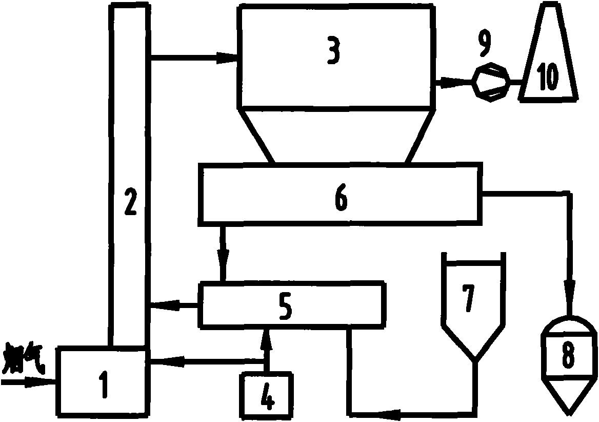
[0020] like figure 1 As shown, a dry flue gas desulfurization, denitrification and dust removal integrated device includes a flue gas drainage device 1, a reactor 2, a dust collector 3, an induced draft fan 9 and a chimney 10 connected in sequence, and also includes a circulating ash fluidization bin 6, Humidification digester 5, denitrification additive storage bin 4, desulfurization absorbent storage bin 7, the circulating ash fluidization bin 6 is located at the bottom of the dust collector 3, and the output end of the circulating ash fluidization bin 6 is connected to the humidification digester 5, the output end of the desulfurization absorbent storage bin 7 is also connected to the input end of the humidification digester 5, and the output end of the denitrification additive storage bin 4 is connected to the inlet of the humidification digester 5 and the flue gas drainage device 1 At least one of the circulating ash fluidization bins 6 is also connected to an ash conveyi...


PUM


Abstract

The invention discloses a dry-type flue gas desulphurization, denitration and dedusting integrated device and method. The integrated device comprises a flue gas guide device, a reactor, a dedusting device, a draught fan and a funnel which are sequentially connected, as well as a circulation dust fluidization cabin, a humidifying digester, a denitration additive storage bin and a desulphurization absorbent storage bin. The circulation dust fluidization bin is arranged at the bottom of the dedusting device, the output end of the circulation dust fluidization bin is connected with the input end of the humidifying digester, and the output end of the desulphurization absorbent storage bin is also connected with the input end of the humidifying digester. The output end of the denitration additive storage bin is connected with at least one of the input end of the humidifying digester and the flue gas guide device. The invention has the advantages of simple process, small occupation, low one-time investment and low operating cost, the SO2 removing efficiency is 80 to 95%, the NOx removing efficiency is 40 to 65%, and the dust emission concentration is less than 50 mg/Nm<3>. The desulphurization and denitration efficiency of the invention can meet the requirement of environmental protection, the running resistance of the device is low, and no sewage generates during the desulphurization and denitration processes. The final product is dry powder and can not cause any secondary pollution, the flue gas can be directly discharged without the need of heat exchange, and the added denitration additive has the synergistic effect with the absorbent to strengthen the removing of the SO2, thereby enhancing the desulphurization efficiency.

Description

【Technical field】 [0001] The invention relates to the field of environmental protection equipment, in particular to an integrated device and method for dry flue gas desulfurization, denitrification and dust removal. 【technical background】 [0002] SO Contained in Today's Coal-fired Flue Gas 2 and NO X The emission of acid rain is the main cause of acid rain and acid rain pollution, causing great harm to human living environment and human health. Therefore, effective removal of both is the top priority in flue gas pollution control. At present, my country's SO in flue gas 2 and NO X Removal is carried out separately, and each has its own mature treatment system and process flow. For flue gas desulfurization alone, the best and feasible wet desulfurization processes mainly include limestone / gypsum method, ammonia method, magnesium method, seawater desulfurization method, etc. Dry or semi-dry desulfurization processes mainly include circulating fluidized bed method, humidi...

Claims


Application Information

Patent Timeline
IPC IPC(8): B01D53/81B01D53/60
CPCY02A50/20
Inventor 李文勇葛介龙王少权张永孟银灿斯洪良方培根陈楼阳李卫忠杨涛
Owner 浙江菲达脱硫工程有限公司
Why Eureka
Try Eureka