Concrete pipe platform vibration moulding process and device thereof

A vibration molding and vibration device technology, applied in reinforcement molding, ceramic molding machines, manufacturing tools, etc., can solve the problems of poor resonance effect, high rigidity, high energy consumption, etc., to reduce production costs, low power, and low power consumption. Effect

Inactive Publication Date: 2011-03-30
朝阳市天龙大型水泥管道(集团)有限公司
View PDF0 Cites 13 Cited by
  • Summary
  • Abstract
  • Description
  • Claims
  • Application Information

AI Technical Summary

Problems solved by technology

This kind of conductive part has the disadvantages of high rigidity, high frequency change, short life, high energy consumption and poor resonance effect; the mechanical vibrator used for vibrating the forming platform is in the form of omnidirectional vibration, which is

Method used


Image

  • Concrete pipe platform vibration moulding process and device thereof
  • Concrete pipe platform vibration moulding process and device thereof
  • Concrete pipe platform vibration moulding process and device thereof

Examples


Embodiment 1

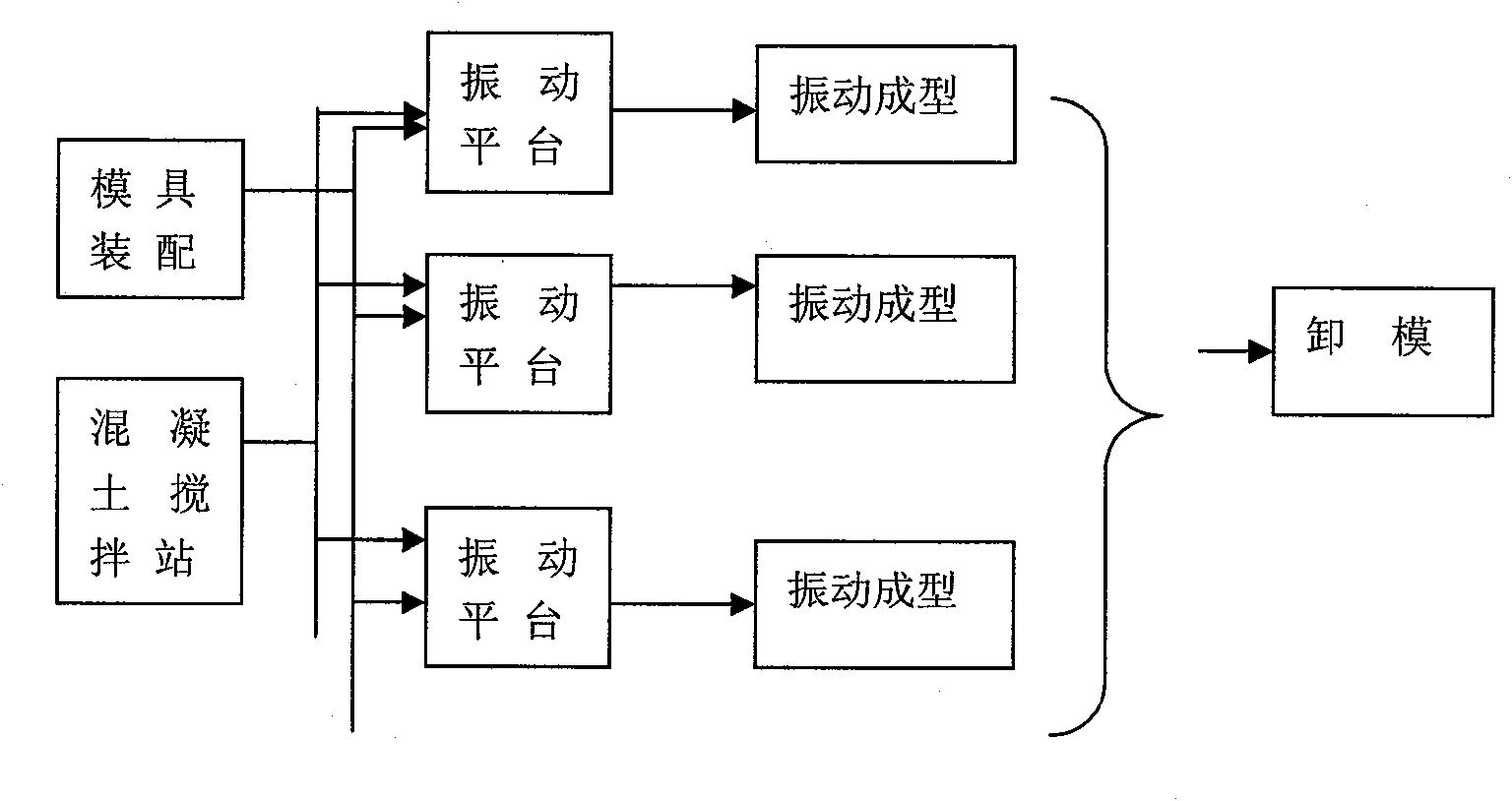
[0026] Example 1: Three-station vertical vibrating concrete pipe production line.

[0027] Concrete mixing station is 1m 3 A set of two.

[0028] Mold assembly can generally be assembled on the vibrating platform or outside the vibrating platform.

[0029] Two groups of 4500×4500mm and one group of 3000×3000mm are installed on the vibration platform at the same time.

[0030] This production line can produce all types (φ1000-φ3600mm) pipes of vertical vibration forming.

[0031] Process concrete steps of the present invention:

[0032] a. Set up the vibration platform: choose a flat desktop fixed platform. The vibration source is a mechanical vibrator. The selection of platform specifications and vibration machine energy should generally consider product specifications, and products can be divided into large, medium and small, that is, large and medium specifications φ2200~3600mm and medium and small specifications φ1000~2000mm. The external dimension of the vibrating pl...

Embodiment approach

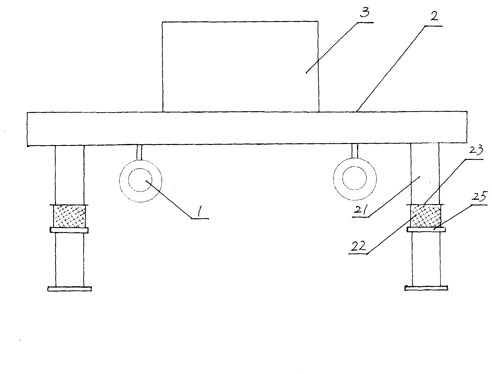
[0041] Such as figure 1As shown, the vibrating table of the device of the present invention is composed of platen 2 and supporting legs 21 to form a vibrating platform, so that the platen and supporting legs 21 are integrated, and the mold 3 to be vibrated is placed on the table; motor 15 kilowatts) mechanical vibrating machine 1, when vibrating machine 1 was running, the eccentric wheel on the output shaft of the vibrating machine drove the platen to vibrate, and the mold 3 placed on the table top also vibrated synchronously with the platen; A vibrating rubber pier 22 is installed between the legs 21. The vibrating rubber pier 22 is cylindrical and is made of natural rubber or reclaimed rubber; an upper and lower guard plate 23 is set on the contact surface between the rubber pier and the supporting leg 21, and the outer edge of the lower guard plate 25 is greater than the peripheral dimension of the vibrating rubber pier 22, and the height of the outer edge is designed to be...


PUM


Abstract

The invention relates to a concrete pipe production process. The process includes the following steps: a vibration platform is set, the vibration platform is a mechanical vibration machine with double amplitude vibration sources and amplitude of 1-2, a movable or nonmovable mould is made, the specification Phi of the mould is 1000-3600mm; concrete is prepared; assembling is carried out and the mould is fixed, namely a core mould and an external mould are lifted and mounted and are connected with the base of the mould, and a skeleton steel bar cylinder mould is placed into the mould, and the mould is fixed on the vibration platform to be poured and vibrated; and a moulding opening is arranged on the vibration platform, and concrete is poured into the mould by virtue of an automatic pouring device. A vibration glue pier is arranged between landing legs of the vibration platform, and swing amplitude of eccentric block is reduced. The invention has high vibration frequency, low energy consumption, reasonable vibration distribution and high product moulding compaction rate, and no undesirable influence can be produced on longitudinal and transverse vibrations; vibration moulding speed is fast, equipment cost thereof is only one fourth that of core mould vibration equipment; besides, motor power is low, vibration time is short, and energy sourced is saved.

Description

technical field [0001] The invention belongs to the technical field of reinforced concrete pipes, in particular to a method and a device for vibration forming of concrete pipe platforms. Background technique [0002] The use of concrete pipes is becoming more and more widely used in various fields such as industry and urban construction. The forming process of concrete pipes is characterized by the need to solve technical problems such as forming, exhaust compaction, and mold replacement. Existing concrete pipe forming processes include centrifugal process, suspension roller process, vertical vibration process, mandrel vibration process and other forms. The pipe has been produced by the traditional high-power rotation or vibration method. It installs the steel skeleton or cage skeleton between the inner and outer molds of the mold, and then places it on the workbench. Using lifting equipment, it passes through the concrete unloading truck. Or the feeding cone to fill the c...

Claims


Application Information

Patent Timeline
IPC IPC(8): B28B21/14B28B21/56B28B11/24
Inventor 赵湘晖赵姗妹赵博平
Owner 朝阳市天龙大型水泥管道(集团)有限公司
Why Eureka
Try Eureka