Test method and device for half cell of fluid bed electrode direct carbon fuel cell

A fuel cell and testing method technology, applied in fuel cells, fuel cell additives, measurement devices, etc., can solve the problems of increasing the difficulty of manufacturing electrode plates, processing costs, and difficulty in replacing electrode plates, avoiding electrolyte loss, storage and transportation. Difficulty, the effect of reducing the diffusion resistance

Inactive Publication Date: 2011-04-06
SOUTHEAST UNIV
View PDF3 Cites 10 Cited by
  • Summary
  • Abstract
  • Description
  • Claims
  • Application Information

AI Technical Summary

Problems solved by technology

This structure increases the manufacturing difficulty and processing cost of the electrode plate, and because MCFC uses a three-in-one plate of cathode, diaphragm, and anode, it is also difficult to replace the electrode plate

Method used


Image

  • Test method and device for half cell of fluid bed electrode direct carbon fuel cell
  • Test method and device for half cell of fluid bed electrode direct carbon fuel cell
  • Test method and device for half cell of fluid bed electrode direct carbon fuel cell

Examples


Embodiment 1

[0050] First place the current collector on the bottom of the half-cell, then add a mixture of self-made bamboo activated carbon (0.5mm particle size) and 30g nickel particles (80-160 mesh) into the half-cell, and then fix the porous plate on the air distribution plate 10cm prevent the activated carbon from being suspended on the top of the molten carbonate and cannot contact the nickel particles, then put the auxiliary electrode, reference electrode and carbonate in sequence, and then cover the cover plate to start heating (the heating rate is 10K·min -1 ), the N introduced during the heating process 2 The flow rate is 60mL·min -1 , rise to preset temperature 923K, adjust O 2 , CO 2 and N 2 The flow rates are 10, 20, 275mL min -1 , connect the external circuit to test the half-cell polarization curve, see Image 6 .

Embodiment 2

[0052] First place the current collector on the bottom of the half-cell, then add a mixture of activated carbon fibers (0.5mm in particle size) and 30g of nickel particles (80-160 mesh) into the half-cell, and then fix the porous plate on the air distribution plate at 10cm to prevent Activated carbon is suspended on the top of the molten carbonate and cannot be in contact with the nickel particles, and then the auxiliary electrode, reference electrode and carbonate are placed in sequence, and then the cover plate is put on to start heating (the heating rate is 10K min -1 ), the N introduced during the heating process 2 The flow rate is 60mL·min -1 , up to preset 923K, adjust O 2 , CO 2 and N 2 The flow rates are 10, 20, 275mL min -1 , connect the external circuit to test the half-cell polarization curve, see Figure 7 .

Embodiment 3

[0054] First place the current collector on the bottom of the half-cell, then add a mixture of self-made bamboo activated carbon (0.5mm particle size) and 15g nickel particles (80-160 mesh) into the half-cell, and then fix the porous plate on the air distribution plate 10cm prevent the activated carbon from being suspended on the top of the molten carbonate and cannot contact the nickel particles, then put the auxiliary electrode, reference electrode and carbonate in sequence, and then cover the cover plate to start heating (the heating rate is 10K·min -1 ), the N introduced during the heating process 2 The flow rate is 60mL·min -1 , rise to pre-923K, adjust O 2 , CO 2 and N 2 The flow rates are 10, 20, 275mL min -1 , connect the external circuit to test the half-cell polarization curve, see Figure 8 .


PUM

PropertyMeasurementUnit
particle diameteraaaaaaaaaa

Abstract

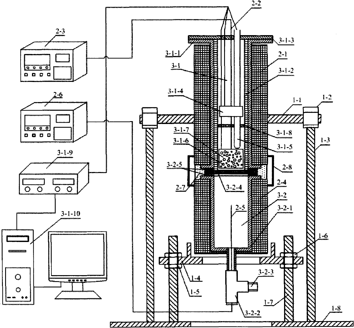
The invention provides a test method and device for half cell of fluid bed electrode direct carbon fuel cell. The method comprises the following steps: firstly, arranging a current collector and the mixture of carbon fuel and catalyst granules in a half cell; secondly, fixing a porous plate in a preset position, and sequentially adding an auxiliary electrode, a reference electrode and carbonate; then, introducing nitrogen gas into the half cell, heating the nitrogen gas to a preset reaction temperature, regulating the flow of the nitrogen gas, and introducing oxygen gas and carbon dioxide into the reference electrode to balance the gas; and finally, connecting to an external circuit to start experiment. The device for realizing the testing method is a half-cell reaction device and comprises a half-cell reactor and a gas preheater, two electric heating devices are respectively used for carrying out temperature control on the half-cell reactor and the gas preheater, and a rotatable support structure is used for supporting and fixing the half-cell reaction device and the electric heating devices and realizing the dumpage of molten carbonate in the half cell. By making full use of theadvantages of the fluid bed electrode and the direct carbon fuel cell, the performance of the cell can be improved.

Description

technical field [0001] The invention relates to a test method and device for a fluidized bed electrode direct carbon fuel cell half cell, belonging to the field of fuel cells. Background technique [0002] In today's global energy shortage and high oil prices, it is imperative to find new energy as a substitute for fossil fuels. Fuel cell is the fourth-generation power generation technology after hydropower, thermal power and atomic power generation. It is also the only power device with pollution-free, high-efficiency, wide application, no noise and continuous work. It is considered to be the most promising power plant in the 21st century. High-efficiency and clean power generation technology with promising development prospects. In traditional energy utilization, the energy conversion method is as follows: chemical energy → thermal energy → mechanical energy → electric energy, limited by the Carnot cycle and energy conversion efficiency, the actual power generation effici...

Claims


Application Information

Patent Timeline
Patent Type & Authority Applications(China)
IPC IPC(8): G01R31/36H01M8/04H01M8/04701
CPCY02E60/50
Inventor 仲兆平张居兵
Owner SOUTHEAST UNIV
Why Eureka
Try Eureka