
Purification method of converter gas

A converter gas and gas technology, applied in chemical instruments and methods, separation methods, manufacturing converters, etc., can solve the problems that cannot meet the requirements of chemical production, contain a large amount of impurities, etc., meet the requirements, remove high precision, and simple process Effect

Active Publication Date: 2011-05-25
SOUTHWEST RES & DESIGN INST OF CHEM IND
View PDF3 Cites 8 Cited by
  • Summary
  • Abstract
  • Description
  • Claims
  • Application Information

AI Technical Summary

Problems solved by technology

[0006] The purpose of the present invention is to overcome the deficiency that converter gas still contains a large amount of impurities after purification in the prior art and cannot meet the requirements of chemical production, and provides a method for purifying converter gas

Method used


Image

  • Purification method of converter gas
  • Purification method of converter gas
  • Purification method of converter gas

Examples


Embodiment 1

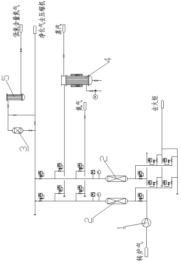
[0023] Embodiment 1: as figure 1 Shown, a kind of purification method of converter gas comprises the following steps:

[0024] Converter gas 500Nm 3 / h After being washed with water to remove dust and cool down, and then pressurized to 1.5MPa by a blower, it is sent to the second tower pressure swing temperature swing adsorption device. The variable pressure and temperature device consists of two adsorption beds to form a continuous operation system, each of which must undergo the following steps in a cycle:

[0025] (1) Adsorption

[0026] The converter gas is fed into the adsorption bed from bottom to top for adsorption, and the purified gas is discharged from the top of the bed. When the leading edge of the adsorption zone moves upwards to a certain position in the bed, after the sulfur, phosphorus, arsenic and their compounds reach the specified concentration in the purified gas, the converter gas enters and the adsorption is stopped. At this time, the raw material gas ...

Embodiment 2

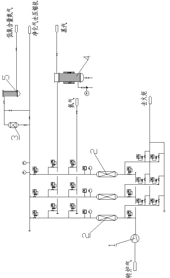
[0039] Embodiment 2: as figure 2 Shown, a kind of purification method of converter gas comprises the following steps:

[0040] 3000Nm 3 The converter gas per hour is washed and dedusted in two stages, cooled, and then pressurized to 0.05MPa by a blower before being sent to a three-tower pressure-swing temperature-swing adsorption device.

[0041] The three-tower variable pressure and temperature device consists of three adsorption beds to form a continuous operation system, each of which must undergo the following steps in a cycle:

[0042] (1) Adsorption

[0043] The converter gas is fed into the adsorption bed from bottom to top for adsorption, and the purified gas is discharged from the top of the bed. When the leading edge of the adsorption zone moves upwards to a certain position in the bed, after the sulfur, phosphorus, arsenic and their compounds reach the specified concentration in the purified gas, the converter gas enters and the adsorption is stopped. At this ti...


PUM


Abstract

The invention discloses a purification method of converter gas. The method comprises the following steps: 1) air entrainment: pressurizing converter gas after dust removal and temperature reduction, delivering the pressurized converter gas to a temperature swing adsorption unit; 2) temperature swing adsorption: sending to the gas treated by the step 1) to an adsorption bed to remove sulphur, phosphorus and arsenic of the gas through pressure swing and temperature swing adsorption, wherein the adsorbent in the adsorption bed uses activated carbon, silica gel or aluminum oxide as carrier which is loaded with 0.1-15wt% of one or more of the compounds of potassium, sodium, calcium, magnesium, zinc, iron or copper; and 3) fine arsenic removal: sending the gas treated by the step 2) to a fixed bed reactor to perform catalytic absorption and remove arsenic compounds in the mixed gas. The purification method of the invention has clever conception, simple process and low investment and can effectively reduce the contents of poisonous and harmful impurities in converter gas and meet the requirements of chemical production on the raw material.

Description

technical field [0001] The invention relates to a method for purifying converter gas, in particular to an adsorption, separation and purification method for converter gas. Background technique [0002] Converter gas is the waste gas discharged during the metallurgical process using the converter. A large amount of converter gas is produced during the converter smelting process, and its main components are CO, CO 2 and N 2 , where the CO content is 60-80%, and the average calorific value is about 8000kJ / m3, which is a very ideal chemical raw material gas and fuel gas. Converter gas not only has great economic value, but also can reduce environmental pollution through recovery and utilization of converter gas, so the recovery and utilization of converter gas is a very important issue. [0003] At present, the commonly used methods for purification and recovery of converter gas mainly include: Lurgi-Thyssen method, LT method for short, which is a converter gas recovery proces...

Claims


Application Information

Patent Timeline
IPC IPC(8): C21C5/40B01D53/04B01D53/86B01D53/46
Inventor 杨云李克兵刘厚阳刘照利潘锋
Owner SOUTHWEST RES & DESIGN INST OF CHEM IND
Learn More