Optimized distribution method for energy of liquid crystal adaptive optical system

A liquid crystal adaptive and optical system technology, applied in the field of adaptive optics, to achieve the effects of reducing residual error, improving correction effect, and improving detection sensitivity

Active Publication Date: 2011-05-25
CHANGCHUN INST OF OPTICS FINE MECHANICS & PHYSICS CHINESE ACAD OF SCI
View PDF3 Cites 10 Cited by
  • Summary
  • Abstract
  • Description
  • Claims
  • Application Information

AI Technical Summary

Problems solved by technology

[0008] In summary, in order to solve the time problem between the detection branch and the correction imaging branch in the liquid crystal adaptive optics system, the present invention proposes an optimal distribution mode of light energy between the correction imaging branch and the wavefront detection branch, the purpose of which is to A liquid crystal adaptive optic

Method used


Image

  • Optimized distribution method for energy of liquid crystal adaptive optical system
  • Optimized distribution method for energy of liquid crystal adaptive optical system
  • Optimized distribution method for energy of liquid crystal adaptive optical system

Examples


Example Embodiment

[0018] Use a xenon lamp with a spectrum close to white light to couple into a bundle of fibers, each with a fiber core diameter of 25μm and a fiber bundle diameter of 1mm; place the fiber bundle light source at the focal point of the telescope to simulate the imaged object at infinity, and perform indoor Optical fiber bundle adaptive correction imaging experiment:
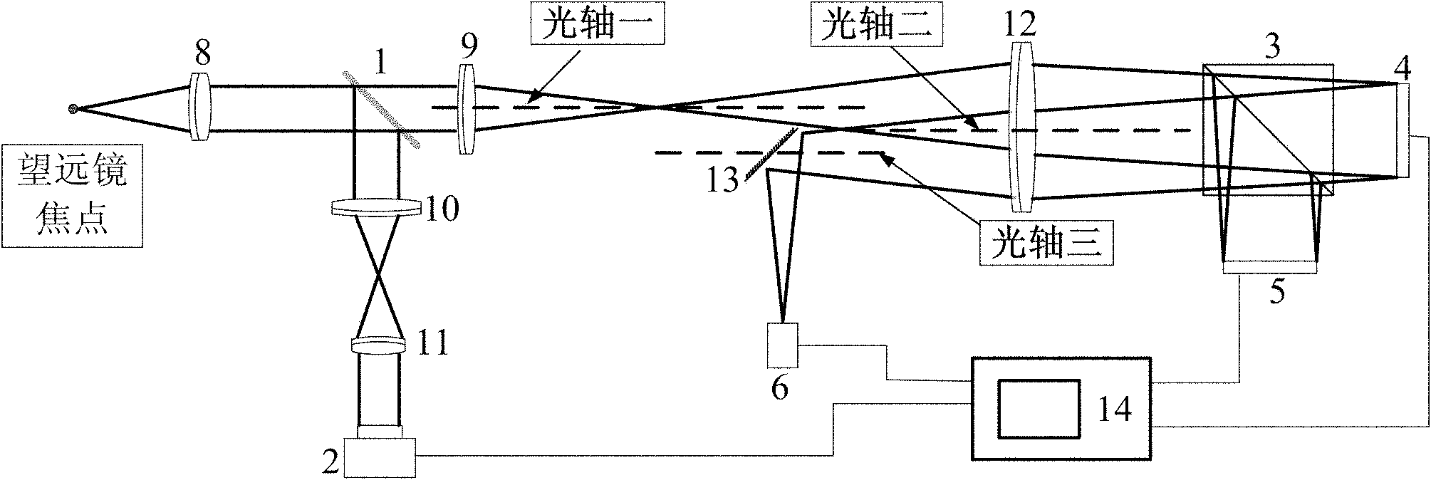
[0019] 1. Follow figure 2 When building an adaptive optical system, regardless of the existence of a telescope, the optical fiber bundle light source is located at the front focus of the first lens 8, forming a closed optical path of the adaptive system. A 40W electric soldering iron is placed behind the first lens 8 and under the beam as a source of thermal interference to cause dynamic distortion of the light wavefront.

[0020] 2. The first lens 8, the second lens 10, the third lens 11, and the fourth lens 9 are all double cemented achromatic lenses, and the surface is coated with anti-reflection coating, the apertu...


PUM

PropertyMeasurementUnit
Caliberaaaaaaaaaa
Focal lengthaaaaaaaaaa

Abstract

The invention belongs to the field of adaptive optics and relates to an optimized distribution method for light energy between a corrosion imaging subcircuit and a wavefront sensing subcircuit in a liquid crystal adaptive optical system. The basic thought of the method is that: the polarizing beam splitting design of the sensing subcircuit and the corrosion imaging subcircuit is changed into spectrophotometry; a beam splitting wavelength is calculated according to a response signal intensity ratio of the receiving terminal devices of the two subcircuits, which is 1:1; the light energy of a wide short wave band with dispersion and a high wave front distortion change speed is distributed to the sensing subcircuit and the light energy of a narrow long wave band without dispersion and with a low wave front distortion change speed is distributed to the correction imaging subcircuit; light in the correction imaging subcircuit is split into two paths of polarized light by using a polarizing beam splitter (PSB), and two liquid crystal correctors are arranged correspondingly; and after correction, a light beam is combined to form an image. The method can improve the sensing capacity of the liquid crystal adaptive optical system considerably, and correspondingly improve the correction speed of the liquid crystal adaptive optical system.

Description

technical field [0001] The invention belongs to the technical field of adaptive optics, and relates to a combination of optical elements such as a liquid crystal corrector, a Hartmann wavefront detector, an adaptive optics controller, a color separation plate, and a PBS beam splitter. A method for optimizing the distribution of light energy between the correction imaging branch and the wavefront detection branch in an adaptive optics system. Background technique [0002] The function of the optical wavefront adaptive correction system is to compensate and correct the distorted wavefront of the incident light in real time to obtain ideal optical imaging. [0003] The liquid crystal corrector of the liquid crystal adaptive optics system adopts microelectronics technology, utilizes the characteristics of high pixel density of liquid crystal devices, has high correction precision, and has a mature manufacturing process. Therefore, the adaptive system of the liquid crystal correc...

Claims


Application Information

Patent Timeline
IPC IPC(8): G02B26/06G01J9/00
Inventor 宣丽穆全全曹召良胡立发彭增辉刘永刚李大禹鲁兴海
Owner CHANGCHUN INST OF OPTICS FINE MECHANICS & PHYSICS CHINESE ACAD OF SCI
Why Eureka
Try Eureka