
Millimeter-wave frequency multiplier and cascaded frequency multipliers

A frequency multiplier and millimeter wave technology, used in power oscillators, electrical components, etc., can solve problems such as high requirements for low power consumption, inability to meet system requirements, weak output frequency multiplication signal, etc., and achieve low bias current. , The effect of good harmonic suppression and strong frequency doubling output signal

Inactive Publication Date: 2011-06-22
PEKING UNIV
View PDF3 Cites 31 Cited by
  • Summary
  • Abstract
  • Description
  • Claims
  • Application Information

AI Technical Summary

Problems solved by technology

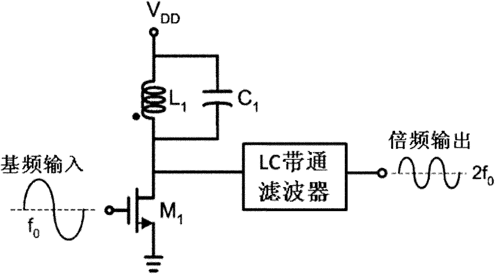
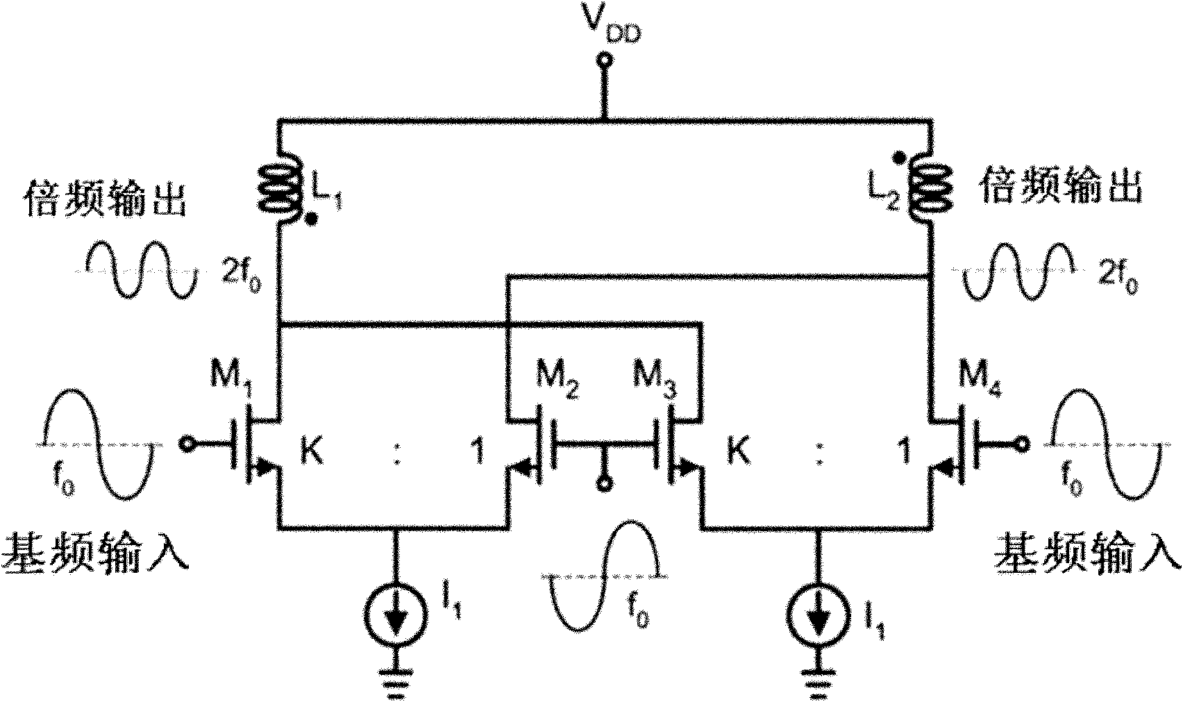
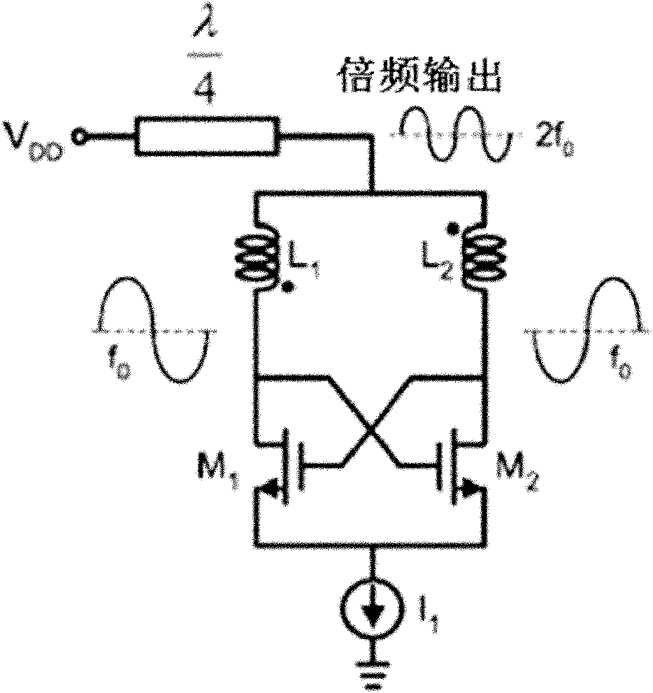
[0004] At present, many frequency multiplier solutions and technologies described in existing literature and patents do not solve the problem of high power consumption, which greatly limits the application of these technologies, such as battery-powered personal mobile terminals The power consumption requirements are very high; although some have the characteristics of low power consumption, the output spectrum is not clean, and the cost of other harmonics is too high to meet the system requirements; the output frequency multiplier signal is too weak, and high power consumption is still required. The frequency amplifier amplifies the frequency multiplied signal, which loses the advantage of low power consumption

Method used


Image

  • Millimeter-wave frequency multiplier and cascaded frequency multipliers
  • Millimeter-wave frequency multiplier and cascaded frequency multipliers
  • Millimeter-wave frequency multiplier and cascaded frequency multipliers

Examples


Embodiment Construction

[0047] In order to describe the present invention in detail, give a following specific embodiment now:

[0048] The novel frequency multiplier of the present invention can be cascaded through Balun phases to form a multi-frequency multiplier. like Image 6 The shown case of a quadruple frequency multiplier realized by the present invention can realize base frequency signal to quadruple frequency signal 4f 0 A transition that includes "Multiplier 1" and "Multiplier 2".

[0049] The "frequency doubler 1" includes transistors Q0 / Q1 and Q4 / Q5, "LC parallel resonant cavity 1", "LC series resonant cavity 1" and "Balun 1"; the "frequency doubler 2" includes Transistors Q2 / Q3 and Q6 / Q7, "LC Parallel Resonator 2", "LC Series Resonator 2" and "Balun 2".

[0050] The "frequency multiplier 1", the input signal is the differential base frequency signal f 0 , the positive terminal is connected to Q0, the negative terminal is connected to Q1, and the output signal is the multiplied signa...


PUM


Abstract

The invention discloses a millimeter-wave frequency multiplier and cascaded frequency multipliers, belonging to the technical field of radio frequency / millimeter wave integrated circuits. The frequency multiplier provided by the invention comprises a pseudo-differential amplifier, an LC parallel resonator cavity and an LC series resonator cavity, wherein the LC parallel resonator cavity is connected between the output end of the pseudo-differential amplifier and a power supply VDD (Voltage Drain Drain), the LC series resonator cavity is connected between the output end of the pseudo-differential amplifier and a ground wire, both input ends of the pseudo-differential amplifier are respectively connected with the positive end and the positive end of an input baseband signal (f0); and the LCparallel resonator cavity has the resonation frequency of 2f0, and the LC series resonator cavity has the resonation frequency of 4f0. The cascaded frequency multipliers provided by the invention comprise a plurality of the frequency multipliers which are sequentially connected through a single-to-double passive transformer. The millimeter-wave frequency multiplier and the cascaded frequency multipliers, provided by the invention, have the advantages of low power consumption, pure frequency spectrum of a frequency-multiplication output signal, good harmonic suppression performance, strong output signal, high frequency and easiness for single-chip integration on a silica-based process.

Description

technical field [0001] The invention belongs to the technical field of radio frequency / millimeter wave integrated circuits, and in particular provides a millimeter wave frequency multiplier and a cascaded frequency multiplier. Background technique [0002] Millimeter waves are radio waves with a wavelength of 1-10 millimeters (frequency 30-300 GHz). Millimeter wave technology can be widely used in satellite communication, navigation, remote sensing and telemetry, astronomical observation and other fields. In recent years, with the rapid development of integrated circuit technology, it has become possible to realize millimeter-wave key circuits and systems on semiconductor integrated circuits and even silicon-based CMOS integrated circuits, thus greatly expanding the application of millimeter-wave technology in people's daily life. Applications, such as 60GHz local point-to-point ultra-high-speed wireless communication, 77GHz car navigation and anti-collision radar, 94GHz mic...

Claims


Application Information

Patent Timeline
IPC IPC(8): H03B19/00H03B19/14
Inventor 叶乐廖怀林王逸潇黄如
Owner PEKING UNIV
Learn More