Method for measuring reflectivity of dual-wavelength high reflecting mirror

A technology of high reflection mirror and measurement method, which is applied in the direction of testing optical performance, etc., and can solve the problems of device adjustment difficulty, reduction of output signal amplitude of optical cavity, and decrease of signal-to-noise ratio

Inactive Publication Date: 2011-07-20
INST OF OPTICS & ELECTRONICS - CHINESE ACAD OF SCI
View PDF10 Cites 17 Cited by
  • Summary
  • Abstract
  • Description
  • Claims
  • Application Information

AI Technical Summary

Problems solved by technology

The invention patent of Chinese patent application number 98114152.8 "a method of measuring high mirror and high reflectivity" uses a pulsed laser system as the light source. The disadvantages of this method are: due to the poor quality of the pulsed laser beam and the existence of mode competition in the ring-down cavity, etc. Factors, the measurement accuracy is restricted, and the cost of the pulse laser used is high, which increases the system cost and is not conducive to popularization and use
The invention patent of Chinese Patent Application No. 200610011254.9 "A Measurement Method of High Mirror Reflectivity" proposes a high reflectivity measurement method using a continuous semiconductor las...

Method used


Image

  • Method for measuring reflectivity of dual-wavelength high reflecting mirror
  • Method for measuring reflectivity of dual-wavelength high reflecting mirror
  • Method for measuring reflectivity of dual-wavelength high reflecting mirror

Examples


Embodiment Construction

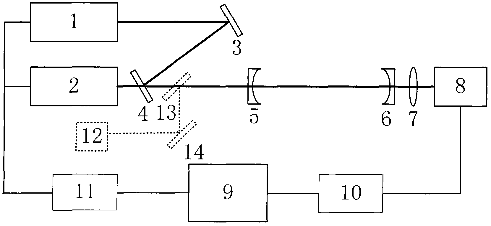
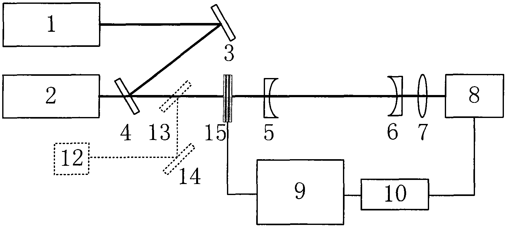
[0037] Attached below figure 1 The measurement system describes the method for measuring the reflectivity of the dual-wavelength high-reflector of the present invention. figure 1 Middle: 1, 2 are laser light sources with two different wavelengths, 3 is a reflector, 4 is a double-beam beam splitter, 5 and 6 are plano-concave dual-wavelength high-reflection mirrors, 7 is a focusing lens, 8 is a photodetector, 9 is a computer, 10 is a data acquisition card, 11 is a function generation card, 12 is a visible auxiliary alignment light source, 13 is a beam splitter, and 14 is a reflector. The thick line in the figure is the optical path, and the thin line is the connection line.

[0038] Both light sources 1 and 2 are continuous semiconductor lasers, and the two semiconductor lasers are output by square wave modulation; the two laser beams are combined through the mirror 3 and the double beam splitter 4, so that they are injected into the ring-down cavity at the same time; two plano-...


PUM


Abstract

The invention discloses a method for measuring the reflectivity of a dual-wavelength high reflecting mirror. The method comprises the following steps: injecting the continuous lasers of two different wavelengths with periodically modulated light intensity into a stable initial optical resonance cavity composed of two or three dual-wavelength high reflecting mirrors at the same time; when the amplitude of the output signal of the initial optical resonance cavity is higher than a set threshold, cutting off the incident laser beam and recording the cavity ring-down signal; or recording the cavity ring-down signal at the falling edge of a modulation signal, and obtaining the ring-down time [tau]01 and [tau]02 of the initial optical resonance cavity at the two laser wavelengths by use of a synchronous measurement method, spectral detection method or alternate measurement method, and calculating the average reflectivity R01 and R02 of a cavity mirror at the two wavelengths; similarly, adding a dual-wavelength high reflecting mirror to be measured into the initial optical resonance cavity according to the using angle so as to form a stable test optical resonance cavity; obtaining the ring-down time [tau]01 and [tau]02 of the test optical resonance cavity at the two laser wavelengths by use of a synchronous measurement method, spectral detection method or alternate measurement method; and obtaining the reflectivity R1 and R2 of the dual-wavelength high reflecting mirror to be measured at the two wavelengths.

Description

technical field [0001] The invention relates to a method and device for measuring the reflectivity of a high reflector, in particular to a method for measuring the reflectivity of a dual-wavelength high reflector. Background technique [0002] In recent years, high-reflectivity thin-film optical components have been increasingly used in large-scale laser systems, laser gyroscopes, gravitational wave measurements, and trace gas detection. The optical cavity ring down technology is currently the main method to accurately measure the reflectivity of high mirrors (Li Bincheng, Gong Yuan; Review of high reflectivity measurement of optical cavity ring down, "Laser and Optoelectronics Progress", 2010, 47: 021203). The invention patent of Chinese patent application number 98114152.8 "a method of measuring high mirror and high reflectivity" uses a pulsed laser system as the light source. The disadvantages of this method are: due to the poor quality of the pulsed laser beam and the ex...

Claims


Application Information

Patent Timeline
IPC IPC(8): G01M11/02
Inventor 李斌成曲哲超韩艳玲
Owner INST OF OPTICS & ELECTRONICS - CHINESE ACAD OF SCI
Why Eureka
Try Eureka